


 397 / 439

b1
b
a1
a
o
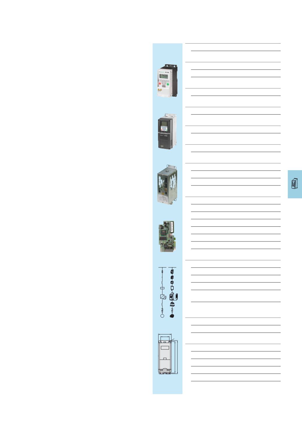
System overview Frequency inverter M-Max™ 10/2 Description Frequency inverter M-Max™ 10/3 Frequency inverters M-Max™ in overview 10/4 Ordering Frequency inverter M-Max™ 10/5 System overview Frequency inverter H-Max™ 10/8 Description Frequency inverter H-Max™ 10/9 Ordering Frequency inverter H-Max™ 10/10 Description Braking resistances 10/13 Interface cards 10/14 Mains chokes, motor chokes 10/16 Ordering Accessories for M-Max™, H-Max™ Braking resistances 10/17 Interface cards 10/18 Radio interference suppression filters 10/19 Enclosure accessories 10/19 Mains chokes 10/20 Motor chokes 10/21 Engineering M-Max™, H-Max™ key to part numbers 10/22 Components of the Power Drives System (PDS) 10/23 Connecting example for M-Max™ 10/26 Assigned switching and protective elements for 10/28 M-Max™ Assigned switching and protective elements 10/30 for H-Max™ Technical data Frequency inverter M-Max™ 10/32 Mains chokes, motor chokes 10/36 Dimensions Frequency inverter M-Max™ 10/38 Frequency inverter H-Max™ 10/39 Braking resistances 10/41 Radio interference suppression filters 10/42 Mains chokes, motor chokes 10/43Frequency inverters
M
3
~
3
~
F
Q
R
R
K
T
M
3
I
OK
BACK
RESET
LOC
REM
R
3