


 400 / 439

10/4
Frequency inverters
M-Max™ frequency inverter
2010
CA08103002Z-EN
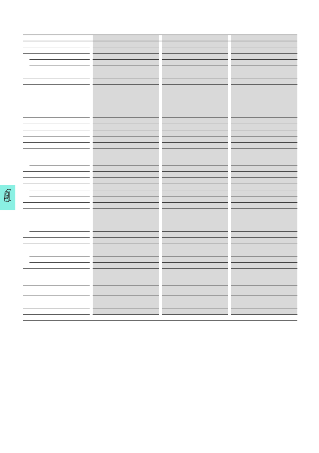
www.eaton.comM-Max™ frequency inverter
MMX12…
MMX32…
MMX34…
Rated operational voltage U
e
230
V
230
V
400
V
System configuration
1
AC 208 V - 15 % … 240 V + 10 % ●
-
-
3
AC 208 V - 15 % … 240 V + 10 % -
●
-
3
AC 380 V - 15 % … 480 V + 10 % -
-
●
Mains frequency
50/60
Hz ±10 %
50/60
Hz ±10 %
50/60
Hz ±10 %
Rated operational current I
e
1.7 - 9.6
A
1)
1.7 - 11
A
1)
1.3 - 14
A
1)
Rated operational current
100 %
I
e
,
continuous current at
max. +50 °C
100 %
I
e
,
continuous current at
max. +50 °C
100 %
I
e
,
continuous current at
max. +50 °C
Starting current
200 %
I
e
for 2 s every 20 s
200 %
I
e
for 2 s every 20 s
200 %
I
e
for 2 s every 20 s
Overload current
150 %
I
e
for 60 s every 600 s
150 %
I
e
for 60 s every 600 s
150 %
I
e
for 60 s every 600 s
Assigned motor rating at rated
operational voltage U
LN
0.25 - 2.2
kW
1)
0.25 - 2.2
kW
1)
0.37 - 7.5
kW
1)
Operating temperature
-10 -
+50 °C
-10 -
+50 °C
-10 -
+50 °C
Operating mode
U/f control, sensorless vector control
U/f control, sensorless vector control
U/f control, sensorless vector control
Pulse frequency (sinusoidal PWM)
1 - 16
kHz (default settings: 6 kHz)
1 - 16
kHz (default settings: 6 kHz)
1 - 16
kHz (default settings: 6 kHz)
Output voltage
0 -
U
LN
V
0 -
U
LN
V
0 -
U
LN
V
Output frequency
0 - 50
Hz (default settings: 50 Hz)
0 - 50
Hz (default settings: 50 Hz)
0 - 50
Hz (default settings: 50 Hz)
Radio interference suppression filter
(
EMC)
Internal
● (for MMX…F…)
● (for MMX…F…)
● (for MMX…F…)
Optional
● (for MMX…N…)
● (for MMX…N…)
● (for MMX…N…)
DC link choke
-
-
-
Protection type
IP20
●
●
●
IP21/NEMA1
● (optional)
● (optional)
● (optional)
IP54
-
-
-
Keypad
●
●
●
Display
LCD, 7 segment
LCD, 7 segment
LCD, 7 segment
Communication interface
Internal
RS485, Modbus RTU,
system interface
RS485, Modbus RTU,
system interface
RS485, Modbus RTU,
system interface
Optional
CANopen or PROFIBUS-DP
CANopen or PROFIBUS-DP
CANopen or PROFIBUS-DP
Control signal terminals
Digital input
6 (
max. +30 V DC, R
i
> 12 kΩ)
6 (
max. +30 V DC, R
i
> 12 kΩ)
6 (
max. +30 V DC, R
i
> 12 kΩ)
Digital output
1 (
max. 48 V DC, max. 50 mA)
1 (
max. 48 V DC, max. 50 mA)
1 (
max. 48 V DC, max. 50 mA)
Analog input
2 (0 -
+10 V, 4 - 20 mA)
2 (0 -
+10 V, 4 - 20 mA)
2 (0 -
+10 V, 4 - 20 mA)
Analog output
1 (0 -
+10 V, max. 10 mA)
1 (0 -
+ 10 V, max. 10 mA)
1 (0 -
+ 10 V, max. 10 mA)
Relays
2 (1
normally open contact, 1 change-
over contact, 250 V, max.°2 A)
2 (1
normally open contact, 1 change-
over contact, 250 V, max.°2 A)
2 (1
normally open contact, 1 change-
over contact, 250 V, max.°2 A)
PID controller
●
●
●
Internal brake chopper
-
-
● (from 3.3 A rated operational
current I
e
)
Production quality
RoHS, ISO 9001
RoHS, ISO 9001
RoHS, ISO 9001
Product standard, regulation
IEC61800-3, UL508C
IEC61800-3, UL508C
IEC61800-3, UL508C
Approval, Certification
CE, UL, cUL, c-Tick
CE, UL, cUL, c-Tick
CE, UL, cUL, c-Tick
Notes
1)
The principle here is that the range is not covered by a single device but by the entire device group.
For specific data of the individual performance values→Ordering
MMX...