


 422 / 439

2010
CA08103002Z-EN
www.eaton.com10/26
Frequency inverters
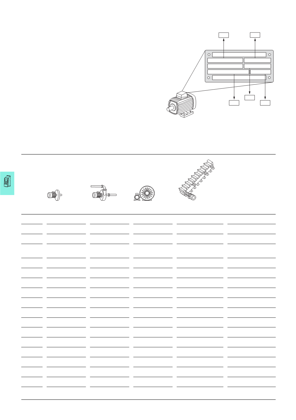
Connection example for M-Max™
Connectionexample forM-Max™
Connecting example for a 0.75 kW
motor with the rating plate
illustrated here
By default, the M-Max™ frequency
inverters are configured so that they
can be operated immediately without
configuration when connected to the
assigned motor rating.
To ensure an optimum operational
behavior, the data on the motor’s
rating label should be entered in the
frequency inverter (electrical image).
The following example shows the
parameters for quick configuration
with the selected drive-specific
parameters for four standard
applications.
1410
min
230/400
V
4.0/2.3
A
50
Hz
-1
0,75
KW cos
v
0.67
P7.5
P7.1
P7.3
P7.6
P7.4
Parameters Basic
(
Standard drive)
Pump drive
Fan drive
Feed unit
(
high load)
Designation
P1.1
1
= Only quick
configuration parameters
1
= Only quick
configuration parameters
1
= Only quick
configuration parameters
1
= Only quick
configuration parameters
Parameter range
P1.2
0
= Basic
1
= Pump drive
2
= Fan drive
3
= Feed unit
(
High load)
Application
P 1.3
0
= EU
0
= EU
0
= EU
0
= EU
Default settings
country-specific (EU/USA)
P6.1
1
= Control signal
terminals (I/O)
(
Input/Output)
1
= Control signal
terminals (I/O)
(
Input/Output)
1
= Control signal
terminals (I/O)
(
Input/Output)
1
= Control signal
terminals (I/O)
(
Input/Output)
Control level
P6.2
3
= AI1
(
analog setpoint value 1)
3
= AI1
(
analog setpoint value 1)
3
= AI1
(
analog setpoint value 1)
3
= AI1
(
analog setpoint value 1)
Setpoint input
(0 - 10
V) terminal 2
P6.3
0.00
Hz
20.00
Hz
20.00
Hz
0.00
Hz
Minimum frequency
P6.4
50.00
Hz
50.00
Hz
50.00
Hz
50.00
Hz
Maximum frequency
P6.5
3.0
s
5.0
s
20.0
s
1.0
s
Acceleration time (acc1)
P6.6
3.0
s
5.0
s
20.0
s
1.0
s
Deceleration time (dec1)
P 6.7
0
= Ramp
(
Acceleration)
0
= Ramp
(
Acceleration)
0
= Ramp
(
Acceleration)
0
= Ramp
(
Acceleration)
Start function
P6.8
0
= Free coasting
1
= Ramp
(
deceleration)
0
= Free coasting
0
= Free coasting
Stop function
P7.1
I
e
I
e
I
e
I
e
Motor, rated operational
current
2)
P7.3
1440
rpm
1440
rpm
1440
rpm
1440
rpm
Motor, rated speed
(
rpm)
2)
P7.4
0.85
0.85
0.85
0.85
Power factor of the
motor (cos ϕ)
2)
P7.5
230/400
V
1)
230/400
V
1)
230/400
V
1)
230/400
V
1)
Motor, rated operational
voltage
P7.6
50.00
Hz
50.00
Hz
50.00
Hz
50.00
Hz
Motor, rated frequency
P11.7
0
= Deactivated
0
= Deactivated
0
= Deactivated
1
= Enabled
Torque increase
M1.1
0.00
Hz
0.00
Hz
0.00
Hz
0.00
Hz
Output frequency
Notes
1)
230
V = MMX12…, MMX32…; 400 V = MMX34…
2)
Depending on output