


 423 / 439

2010
CA08103002Z-EN
www.eaton.comFrequency inverters
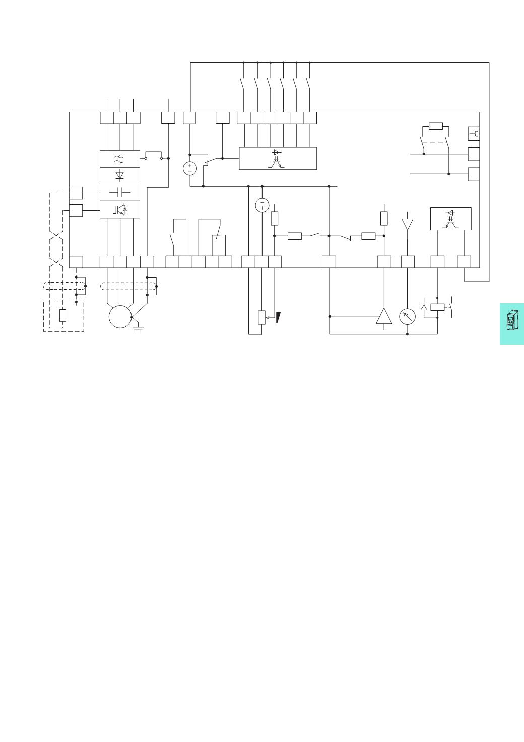
Connection example for M-Max™
10/27
Connectionexample forM-Max™
Block diagram MMX32 and MMX34
Terminals R+ and R- for external braking resistor (optional), only with MMX34…4D3…, MMX34…5D6…, MMX34…7D6…, MMX34…9D0, MMX34…012… and
MMX34…014…
PE
e
R+
R-
a
Error
Run
Ready
3
AC
3
AC
23 22
PE
PE
W V U
M
3
~
X1
A
B
e
24 26
25
1 2
3
5
4
AO
0 (4)...20
mA
0...
+10 V < 10 mA
7
8 9
18
DI1
DI2
AI1
DI3
DI4
DI5
DI6
GND
DI_COM
< 10 mA
+10 V Out
14 15 16
10
R13
R14
R21
R22
R24
S4
S3
S2
S1
FWD
REV
FF1
FF2
24
V
6
< 50 mA
+24 V Out
GND
120
O
< 50 mA
DO-
DO+
13
20
+
0...
+10 V
L1
L3
200
k
O
200
k
O
200
O
200
O
AI2
f-Out
PI-Ist
EMC
Reset
PI-Off
f-Soll
L2/N
The control signal terminals have the
following default assignment
2:
AI1: f-Soll = frequency reference
value
(0 -
+10 V)
4:
AI2: PI-Ist = PID controller actual
value
(
Process variable, 4 - 20 mA)
8:
DI1: FWD = enable forward
(
clockwise rotating field)
9:
DI2: REV = enable reverse
(
counterclockwise rotating field)
10:
DI3: FF1 = Fixed frequency 1
13:
DO-: Ready = Ready for operation
(
transistor output with voltage of
terminal 20)
14:
DI4: FF2 =
Fixed frequency
2
15:
DI5: Reset = Error message
acknowledge
16:
DI6: PI-Off = PID controller disabled
18:
AO: f-Out = output frequency to
motor (0 – +10 V)
20:
DO+: input voltage for transistor
output
22/23:
R13/R14: RUN = run signal (relay)
24/25/26:
R21/R22/R24: Error = error message
(
relay)
The function of the digital inputs and outputs,
and the scaling of the analog inputs and
outputs are defined with parameters. These
are described in manual AWB8230-1603.