


 420 / 439

2010
CA08103002Z-EN
www.eaton.com10/24
Frequency inverters
General information about engineering information
General informationaboutengineering information
Electrical mains connection
M-Max™ and H-Max™ frequency
inverters can be connected and
operated on star-point-grounded
AC mains (according to IEC 60364)
without limitation.
Connection and operation on
asymmetrically grounded networks,
such as phase-grounded delta (USA)
or non-grounded or high-resistance-
grounded (> 30 Ω) IT systems is
permitted with limitations. In these
networks only frequency inverters
without integrated radio interference
suppression filters (EMC) must be
used. On devices with integrated radio
interference suppression filter the
filer’s ground connection must be
disconnected.
The standardized rated operational
voltages of the utility companies fulfil
the following conditions at the point of
transfer to the consumer:
•
Maximum deviation from the rated
voltage (U
LN
):
±10 %
•
Maximum deviation in the voltage
symmetry: ±3 %
•
Maximum deviation from the rated
frequency: ±4 %
Regarding the lower voltage value
(
U
LN
-10 %)
of the mains voltage, a
further voltage drop of 4 percent in the
consumer networks is permissible.
The power supply voltage at the
consumer must have a value of
U
LN
-14 %.
In ring-operated mesh networks
(
such as in the EU) the standardized
consumer voltages (230/400/690 V) are
identical with the utility company’s
supply voltages. In star networks (for
example in North America/USA), the
stated consumer voltages take the
voltage drop from the utility company’s
infeed point to the last consumer into
account.
The wide tolerance band of the
frequency inverters of the M-Max™
and H-Max™ series takes all known
deviations from the standardized rated
operational voltages worldwide into
account (IEC 60038):
230
V: 208 V -15 % - 240 V +10 %
400
V: 380 V -15 % - 480 V +10 %
The permissible frequency range is
50
Hz -10 % – 60 Hz +10 %.
Safety and switching
The mains-side components are
assigned according to the frequency
inverter’s input-side rated operational
current I
LN
and utilization category
AC-1.
Fuses, circuit-breakers and conductor
cross-sections must meet the national
and regional requirements and the
required approvals at the point of
operation.
For fire prevention and the protection
of persons and domestic animals from
excessive contact voltages residual-
current devices (RCD) must be used.
In combination with a frequency
inverter only AC/DC sensitive RCDs
(
Type B) must be used.
Identification on the residual-
current circuit-breakers
AC/DC sensitive (RCD, type B)
With frequency-controlled power
drive systems (PDS), leakage currents
to ground occur. The main causes are
external capacitances between the
phases of the motor cable, the motor
cable shielding, Y capacitors in the
frequency inverter and radio inter-
ference suppression filters and
grounding measures at the motor’s
site of operation. These leakage
currents can exceed 3.5 mA and
require increased grounding of the
PDS according to EN 50178 (ground
conductor cross-section ≥ 10 mm
2
).
EMC measures
Frequency inverters work with fast
electronic switches (IGBT) in the
inverter. This can cause radio inter-
ference in a PDS, which, in turn, can
adversely affect nearby electronic
equipment. To provide protection from
this high-frequency interference,
these should be spatially separated
and shielded from frequency-
controlled PDS.
In Europe, adherence to the EMC
Directive is mandatory. The EMC
product standard for power drive
systems (PDS) is IEC/EN 61800-3. This
standard covers the complete drive
system, from mains infeed to the
motor.
Both versions of the frequency
inverters of theM-Max™and H-Max™
series (with built-in and external radio
interference suppression filter) fulfil
the requirements of the EMC product
standard for residential areas (first
environment), and therefore also for
the higher limit values in industrial
areas (second environment).
L2
N
L1
L3
PE
L2
PEN
L1
L3
Supply voltage U
LN
of the
utility company
Motor voltage according
to UL 508 C
Consumer voltage, rated
value for the motors
120
V
110 - 120
V
115
V
240
V
220 - 240
V
230
V
480
V
440 - 480
V
460
V
600
V
550 - 600
V
575
V
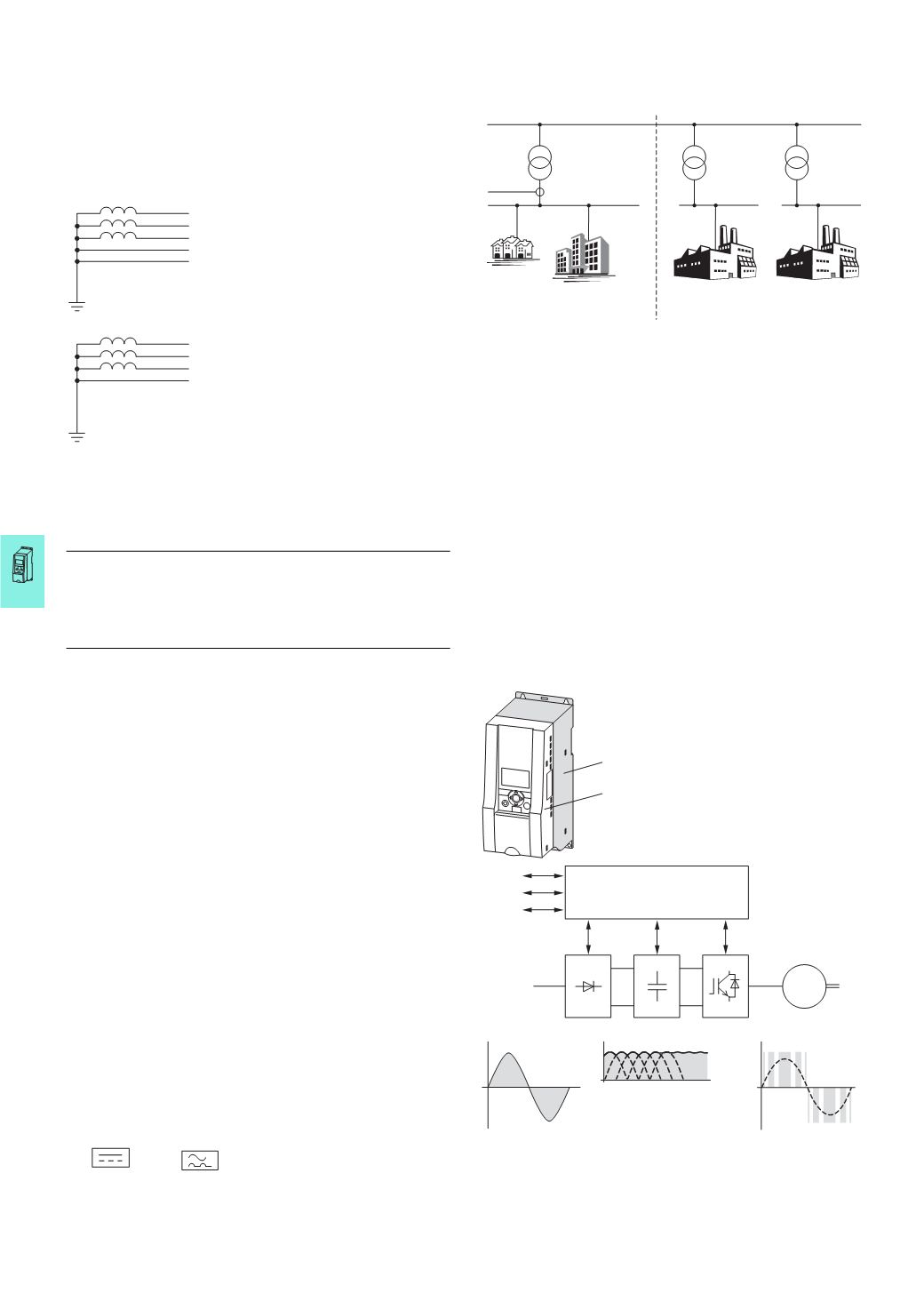
Frequency inverters
The frequency inverter is an electronic
apparatus for controlling variable-
speed drives with three-phase motors.
It is intended for installation in a
machine or for assembly with other
components to a machine or plant. The
main components of a modern
compact frequency inverter are a
power section and a control section.
Example: M-Max™ series
The frequency inverter’s control
section contains a centrally control-
ling microprocessor, through which all
variable values that occur in the
frequency inverter are influenced.
These values and all control functions
are represented as parameters.
The functional control of the frequency
inverter and the output values in the
power section (such as frequency,
voltage and current) can be adjusted
through:
•
control terminals (I/O) with analog
and digital (binary) inputs,
•
a keypad with function keys and
display,
•
serial interfaces (bus) with RS485
(
Modbus RTU) and optional field bus
connections (CANopen,
PROFIBUS-DP, etc.) and an optional
PC connection.
Internal open and closed-loop control
circuits monitor all variable values in
the frequency inverter and auto-
matically switch the process off if a
quantity value reaches a dangerous
level.
The power section of a static and
compact frequency generally consists
of three subgroups:
•
Rectifier (A),
•
Internal DC link (B),
•
Inverter module (C).
The devices of the H-Max™ series
contain a brake chopper as standard.
Depending on their rating, some
devices of the M-Max™ series also
contain a brake chopper.
Public medium-voltage supply grid
Public
low-voltage supply grid
Industry
grid 1
Industry
grid 2
Measuring
point
Category C1
Category C1/C2
Category C3/C4
Category C3/C4
1
st enviroment
2
nd enviroment
I
OK
BACK
RESET
LOC
REM
a
b
①
Power section
with:
A = Rectifier
B = Internal DC link
C = Inverter module
②
Control section
with:
I/O = analog and binary inputs and
outputs
KEYPAD = keypad with display
BUS = serial interfaces
(
RS485, field bus, PC interface)
U
LN
= phase voltagefrom
supplying AC mains
U
DC
= DC link voltage
U
DC
= 1.41 × U
LN
(
single-phase phase voltage)
U
DC
= 1.35 × U
LN
(
three-phase phase voltage)
Output voltage =
switched DC link voltage
with sinusoidal pulse-
width modulation
(
PWM)
Block diagram with main components of a frequency inverter
CPU
A
B
C
BUS
M
3
h
KEYPAD
I/O