


 421 / 439

2010
CA08103002Z-EN
www.eaton.comFrequency inverters
General information about engineering information
10/25
General informationaboutengineering information
Modulation
The IGBTs in the inverter of the
M-Max™ and H-Max™ frequency
inverters are controlled with
sinusoidal pulse-width modulation
(
PWM). Two control methods are
possible:
•
Voltage/frequency (U/f) control,
•
Sensorless vector control (speed
control).
Voltage/frequency control
is the
best-known and most commonly used
method. A simple characteristic curve
(
linear or square) defines the motor’s
rotating field frequency and the
corresponding three-phase line-to-
line voltage of the motor is selected
so that the motor is neither over
magnetized nor under magnetized.
The main fields of application of U/f
control are:
•
Pump and fan drives,
•
Horizontal conveying and transpor-
tation systems,
•
Drives with several motors (parallel
operation of several motors at the
output of a frequency inverter).
In
sensorless vector control
the
magnetic fields of the stator and rotor
windings are aligned so as to oppose
each other. With asynchronous
motors the magnetic flux in the rotor
must be described in an electronic
model of the motor. This requires the
physical parameters on the motor’s
rating plate to be entered.
In vector operation the frequency
inverter can control only one motor.
A parallel operation of several motors
is not possible here. The exact
calculation of the phase voltages at
the frequency inverter’s output,
however, improves the motor’s
operational behavior. The motor also
heats up less in the lower speed range.
The field-oriented vector control
results in a significant improvement
in the drive dynamics as well as
optimizing performance; it also
increases the range of possible
applications.
The main applications of sensorless
vector control are:
•
Material processing machines,
•
compressors,
•
Heavy starting duty (extruders,
agitators, mixers),
•
Horizontal conveying equipment
(
cranes, elevators).
Explanation:
EMC = electromagnetic
compatibility
IGBT = insulated-gate bipolar
transistor
PDS = power drive system
RCD = residual-current device
①
Stator winding
②
Air gap
③
Transformed rotor winding
Simplified equivalent circuit diagram with associated current vectors
R
1
a
c b
X'
2
X
1
i
1
i
w
u
1
X
h
i
m
R'
2
s
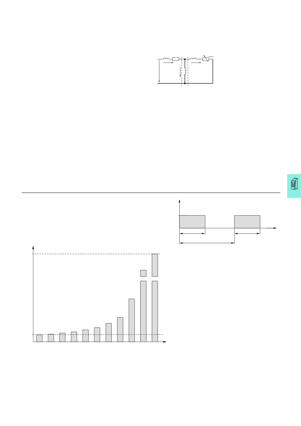
Technical information about the braking resistors
:
The stated ratings P
DB
of the braking resistors apply to continuous operation.
In short-time operation these values can be increased through multiplication with the
type-specific power factor according to the following formula:
P
max
≤ (P
DB
× 100 %) ÷ DF [%]
P
max
= max. pulse rating
P
DB
= continuous rating at a duty factor of 100 %
DF = duty factor
t
c
= cycle time (max. 120 seconds)
The duty factor is given in percent (%) and is calculated with the following formula:
DF [%] = (DF × 100 %) ÷ t
c
P
DB
ED
P
max
1
2
6
1.1 1.25 1.4 1.7
2.6
3.4
10
20
100 90 80 70 60 50 40 30 20 10 5
ED [%]
P
DB
t
[
s]
ED
t
C
(
F
120
s)