


 286 / 338

D-52
Additional information
Electrical characteristics
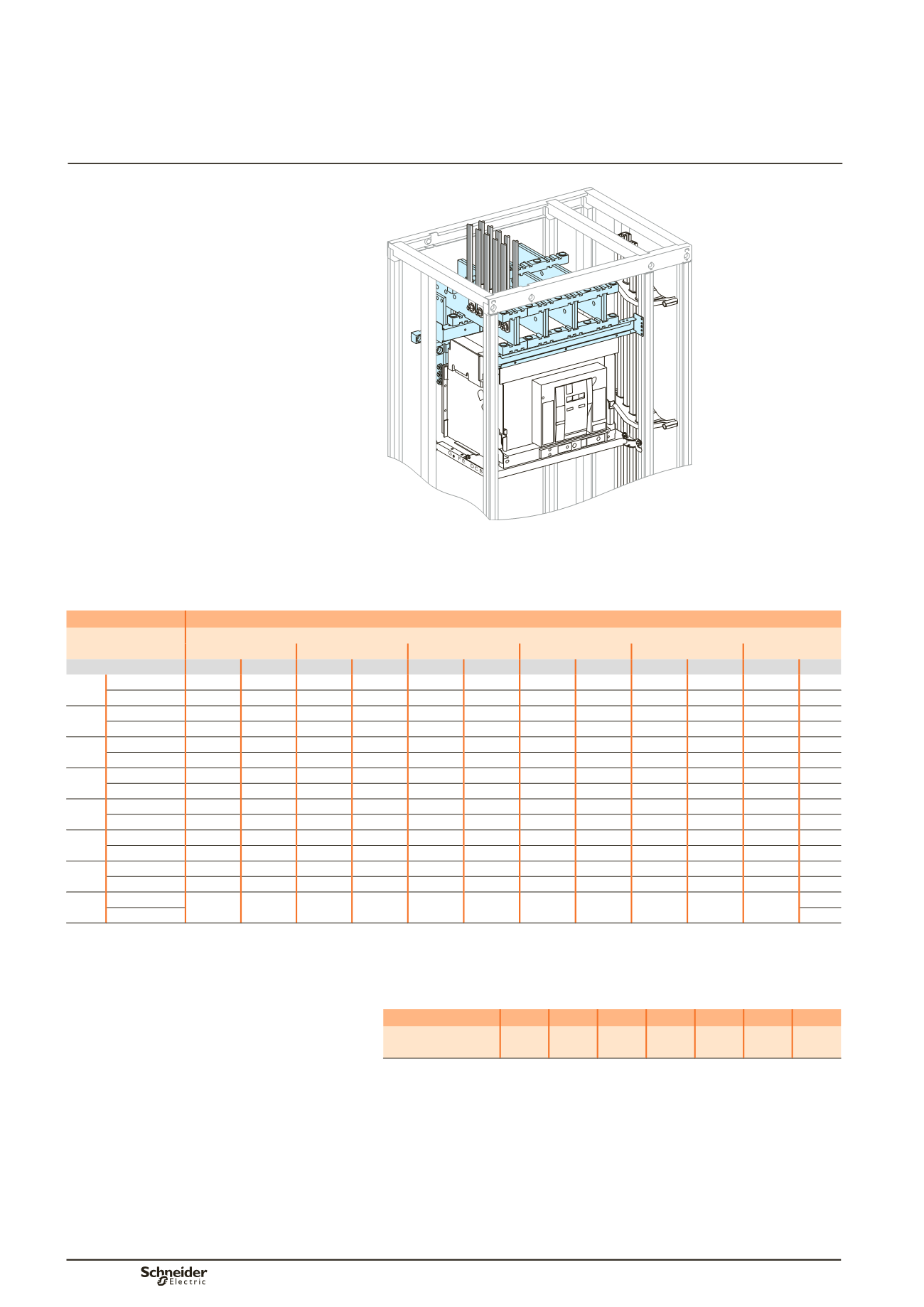
Masterpact NW08 to NW40
Drawout
Vertical mounting
Front or rear connection
Incoming via top or bottom
Busbar drawings supplied by
Schneider Electric
Dd383677.eps
Customer connection
Flat bars, 10 mm thick
Device
Permissible current (A)
Ambient temperature around the switchboard
25 °C
30 °C
35 °C
40 °C
45 °C
50 °C
IP
y
31 IP > 31 IP
y
31 IP > 31 IP
y
31 IP > 31 IP
y
31 IP > 31 IP
y
31 IP > 31 IP
y
31 IP > 31
NW08 Size per phase 1b 60 x 10 1b 60 x 10 1b 60 x 10 1b 60 x 10 1b 60 x 10 1b 60 x 10 1b 60 x 10 1b 60 x 10 1b 60 x 10 1b 60 x 10 1b 60 x 10
bb
I (A)
800
800
800
800
800
800
800
800
800
800
800
NW10 Size per phase 1b 60 x 10 1b 60 x 10 1b 60 x 10 1b 60 x 10 1b 60 x 10 1b 60 x 10 1b 60 x 10 1b 60 x 10 1b 60 x 10 1b 60 x 10 1b 60 x 10
bb
I (A)
1000
1000
1000
1000
1000
1000
1000
1000
1000
1000
1000
NW12 Size per phase 1b 60 x 10 1b 60 x 10 1b 60 x 10 1b 60 x 10 1b 60 x 10 1b 60 x 10 1b 60 x 10 1b 60 x 10 1b 60 x 10 1b 60 x 10 1b 60 x 10
bb
I (A)
1250
1250
1250
1210
1250
1180
1210
1140
1180
1100
1140
NW16 Size per phase 1b 80 x 10 1b 80 x 10 1b 80 x 10 1b 80 x 10 1b 80 x 10 1b 80 x 10 1b 80 x 10 1b 80 x 10 1b 80 x 10 1b 80 x 10 1b 80 x 10
bb
I (A)
1560
1480
1520
1430
1480
1380
1430
1330
1380
1280
1330
NW20 Size per phase 2b 80 x 10 2b 80 x 10 2b 80 x 10 2b 80 x 10 2b 80 x 10 2b 80 x 10 2b 80 x 10 2b 80 x 10 2b 80 x 10 2b 80 x 10 2b 80 x 10
bb
I (A)
2000
2000
2000
1950
2000
1900
1950
1830
1900
1760
1830
NW25 Size per phase 2b100 x 10 2b100 x 10 2b100 x 10 2b100 x 10 2b100 x 10 2b100 x 10 2b100 x 10 2b100 x 10 2b100 x 10 2b100 x 10 2b100 x 10
bb
I (A)
2470
2280
2410
2210
2350
2140
2280
2070
2210
2000
2140
NW32 Size per phase 2b120 x 10 2b120 x 10 2b120 x 10 2b120 x 10 2b120 x 10 2b120 x 10 2b120 x 10 2b120 x 10 2b120 x 10 2b120 x 10 2b120 x 10
bb
I (A)
2960
2730
2890
2630
2820
2530
2730
2450
2630
2370
2530
NW40 Size per phase
(2)
(2)
(2)
(2)
(2)
(2)
(2)
(2)
(2)
(2)
(2)
bb
I (A)
(1)
bb
Connection impossible due to the operating-temperature limits of the devices installed in the switchboard.
(1)
For NW40 IP >31, performances realized with forced ventilation.
(2)
Contact Schneider Electric for 4000 A dedicated cubicle
Canalis connection
For Canalis connections, apply the appropriate derating coefficient K.
Device
NW08 NW10 NW12 NW16 NW20 NW25 NW32
Derating
coefficient K
1
1
1
0,98 0,98 0,97 0,97
Note:
the values indicated above have been validated for Prisma P switchboards.
Designingcustomerconnections
Masterpact NW08 to NW40 withdrawable