


 292 / 338

D-58
Additional information
Electrical characteristics
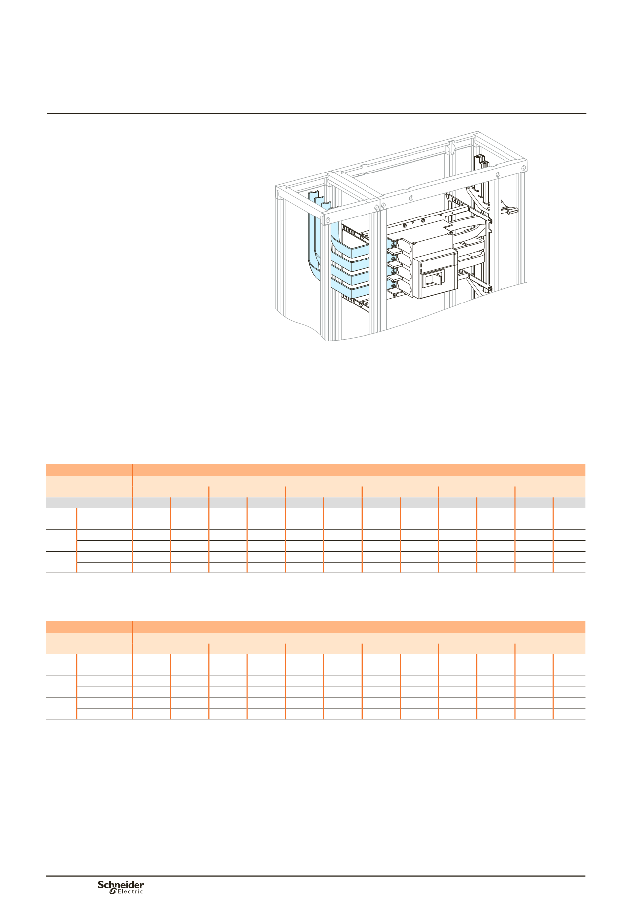
Compact NS630b to NS1000
Horizontal mounting
Front connection
Incoming via top or bottom
Installation on the left or right
Dd383545.eps
Using the data below, it is possible to determine the size of the copper bars and the
maximum permissible currents when making the connections to busbars for a
horizontal, fixed Compact NS630b/NS1600, taking into account the ambient
temperature around the switchboard and the IP value.
Connection to be made according to the busbar drawings supplied.
Customer connection
Flat bars, 5 mm thick
Device
Permissible current (A)
Ambient temperature around the switchboard
25 °C
30 °C
35 °C
40°C
45 °C
50 °C
IP
y
31 IP > 31 IP
y
31 IP > 31 IP
y
31 IP > 31 IP
y
31 IP > 31 IP
y
31 IP > 31 IP
y
31 IP > 31
NS630b Size per phase 2b 50 x 5 2b 50 x 5 2b 50 x 5 2b 50 x 5 2b 50 x 5 2b 50 x 5 2b 50 x 5 2b 50 x 5 2b 50 x 5 2b 50 x 5 2b 50 x 5
bb
I (A)
630
630
630
630
630
630
630
630
630
630
630
NS800 Size per phase 2b 50 x 5 2b 50 x 5 2b 50 x 5 2b 50 x 5 2b 50 x 5 2b 50 x 5 2b 50 x 5 2b 50 x 5 2b 50 x 5 2b 50 x 5 2b 50 x 5
bb
I (A)
800
800
800
800
800
800
800
800
800
800
800
NS1000 Size per phase 2b 50 x 5 2b 50 x 5 2b 50 x 5 2b 50 x 5 2b 50 x 5 2b 50 x 5 2b 50 x 5 2b 50 x 5 2b 50 x 5 2b 50 x 5 2b 50 x 5
bb
I (A)
1000
1000
1000
1000
1000
1000
1000
1000
1000
1000
1000
bb
Connection impossible due to the operating-temperature limits of the devices installed in the switchboard.
Flat bars, 10 mm thick
Device
Permissible current (A)
Ambient temperature around the switchboard
25 °C
30 °C
35 °C
40°C
45 °C
50 °C
NS630b Size per phase 1b 50 x 10 1b 50 x 10 1b 50 x 10 1b 50 x 10 1b 50 x 10 1b 50 x 10 1b 50 x 10 1b 50 x 10 1b 50 x 10 1b 50 x 10 1b 50 x 10
bb
I (A)
630
630
630
630
630
630
630
630
630
630
630
NS800 Size per phase 1b 50 x 10 1b 50 x 10 1b 50 x 10 1b 50 x 10 1b 50 x 10 1b 50 x 10 1b 50 x 10 1b 50 x 10 1b 50 x 10 1b 50 x 10 1b 50 x 10
bb
I (A)
800
800
800
800
800
800
800
800
800
800
800
NS1000 Size per phase 1b 50 x 10 1b 50 x 10 1b 50 x 10 1b 50 x 10 1b 50 x 10 1b 50 x 10 1b 50 x 10 1b 50 x 10 1b 50 x 10 1b 50 x 10 1b 50 x 10
bb
I (A)
1000
1000
1000
1000
1000
1000
1000
1000
1000
1000
1000
bb
Connection impossible due to the operating-temperature limits of the devices installed in the switchboard.
Note:
the values indicated above have been validated for Prisma P switchboards.
Designingcustomerconnections
Fixed Compact NS630b to NS1000
Horizontal mounting