


 294 / 338

D-60
Additional information
Electrical characteristics
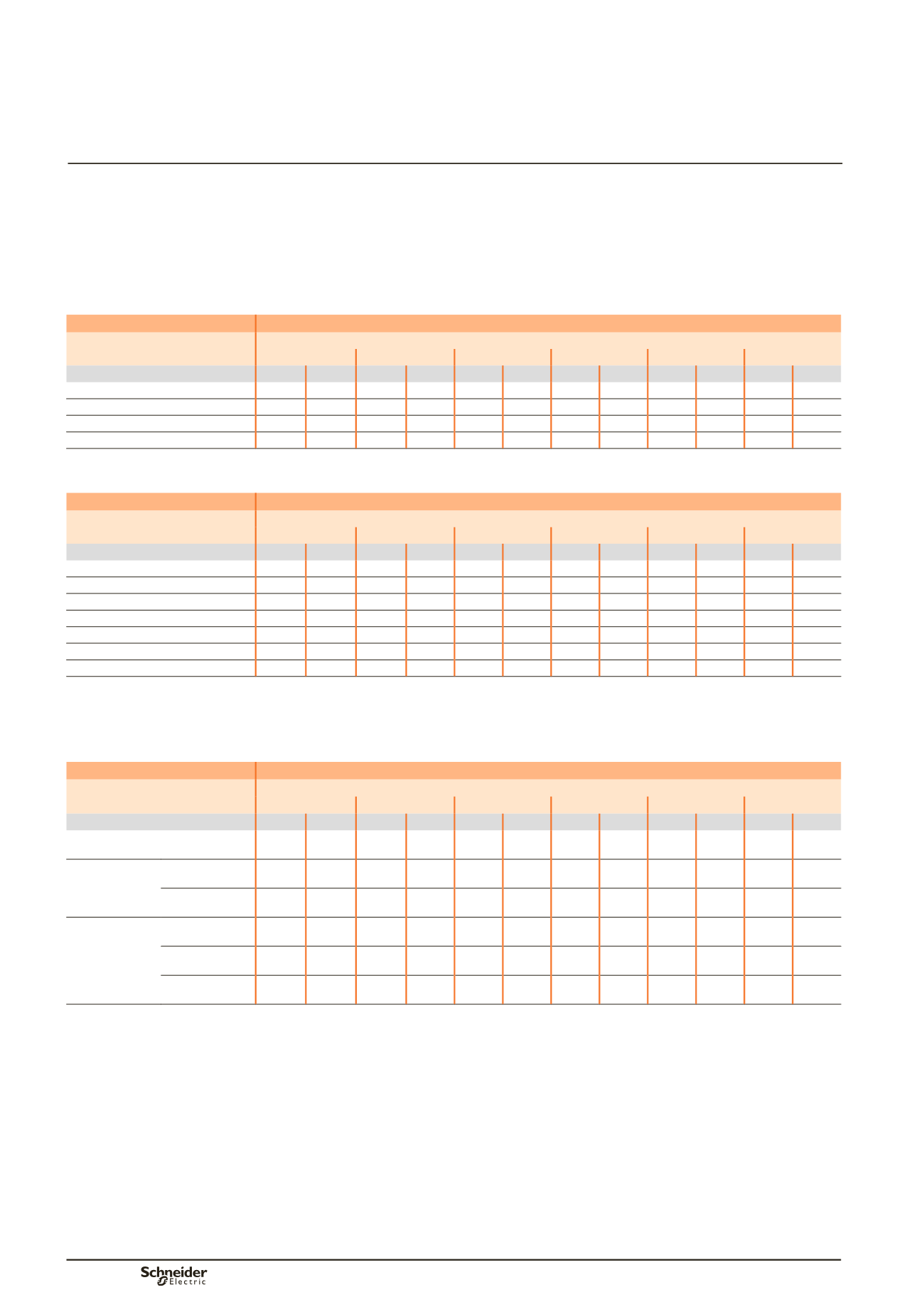
Permissible current and selection of horizontal Linergy BS
busbars
The goal is to optimise busbar size according to the installation and operating
criteria.
Horizontal Linergy BS busbars
Fupact INF/ISFT/ISFL
Linergy BS bars, 5 mm thick
Type of bars
Permissible current (A)
Ambient temperature around the switchboard
25 °C
30 °C
35 °C
40 °C
45 °C
50 °C
Size per phase
IP
y
31 IP > 31 IP
y
31 IP > 31 IP
y
31 IP > 31 IP
y
31 IP > 31 IP
y
31 IP > 31 IP
y
31 IP > 31
1 Linergy BS bar, 60 x 5
800
750
760
700 710 650 660 600 610 550 560
bb
1 Linergy BS bar, 80 x 5
1000 910
970
860 910 810 860 750 810 700 750
bb
2 Linergy BS bars, 60 x 5
1400 1250 1320 1160 1250 1070 1160 980 1070 880 980
bb
2 Linergy BS bars, 80 x 5
1700 1500 1600 1400 1500 1280 1400 1160 1280 1030 1160
bb
bb
Connection impossible due to the operating-temperature limits of the devices installed in the switchboard.
Linergy BS bars, 10 mm thick
Type of bars
Permissible current (A)
Ambient temperature around the switchboard
25 °C
30 °C
35 °C
40 °C
45 °C
50 °C
Size per phase
IP
y
31 IP > 31 IP
y
31 IP > 31 IP
y
31 IP > 31 IP
y
31 IP > 31 IP
y
31 IP > 31 IP
y
31 IP > 31
1 Linergy BS bar, 50 x 10
1150 1000 1080 930 1000 850 930 760 850 670 760
bb
1 Linergy BS bar, 60 x 10
1400 1250 1320 1160 1250 1070 1160 980 1070 880 980
bb
1 Linergy BS bar, 80 x 10
1700 1500 1600 1400 1500 1280 1400 1160 1280 1030 1160
bb
2 Linergy BS bars, 50 x 10
1940 1690 1840 1560 1700 1420 1560 1270 1420 1100 1270
bb
2 Linergy BS bars, 60 x 10
2170 1900 2040 1750 1900 1590 1750 1420 1590 1240 1420
bb
2 Linergy BS bars, 80 x 10
2670 2340 2500 2160 2340 1970 2160 1770 1970 1550 1770
bb
2 Linergy BS bars, 100 x 10
3120 2750 2930 2520 2750 2310 2520 2070 2310 1820 2070
bb
bb
Connection impossible due to the operating-temperature limits of the devices installed in the switchboard.
Rear horizontal Linergy BS bars
Fupact ISFT/ISFL
Linergy BS bars, 10 mm thick
Device
Permissible current (A)
Ambient temperature around the switchboard
25 °C
30 °C
35 °C
40 °C
45 °C
50 °C
Size per phase IP
y
31 IP > 31 IP
y
31 IP > 31 IP
y
31 IP > 31 IP
y
31 IP > 31 IP
y
31 IP > 31 IP
y
31 IP > 31
ISFT 160
1 bar Linergy BS
30 x 10
730
680
680
630 630 570 570 510 510 450 450
bb
ISFL 160
1 bar Linergy BS
60 x 10
1400 1250 1320 1160 1250 1070 1160 980 1070 880 980
bb
1 bar Linergy BS
80 x 10
1700 1500 1600 1400 1500 1280 1400 1160 1280 1030 1160
bb
ISFL 250/400/630 1 bar Linergy BS
80 x 10
1700 1500 1600 1400 1500 1280 1400 1160 1280 1030 1160
bb
1 bar Linergy BS
100 x 10
2050 1800 1930 1680 1800 1540 1680 1400 1540 1240 1400
bb
1 bar Linergy BS
120 x 10
2390 2100 2250 1950 2100 1800 1950 1630 1800 1440 1630
bb
bb
Connection impossible due to the operating-temperature limits of the devices installed in the switchboard.
Designing busbars
Fupact INF, ISFT, ISFL
Linergy BS busbars