


 290 / 338

D-56
Additional information
Electrical characteristics
Designingcustomerconnections
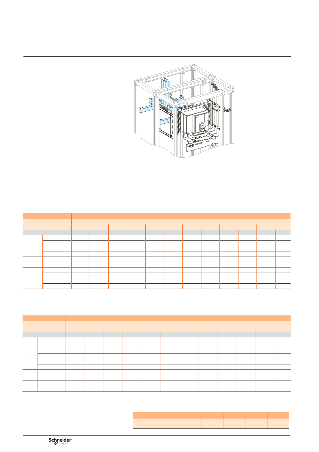
Fixed Compact NS630b to NS1600
Compact NS630b to NS1600
Fixed
Rear connection
Incoming via top or bottom
Busbar drawings supplied by
Schneider Electric
Dd383543.eps
Using the data below, it is possible to determine the size of the copper bars and the
maximum permissible currents when making a rear customer connection for a
vertical, fixed Compact NS630b/NS1600, taking into account the ambient
temperature around the switchboard and the IP value.
Connection to be made according to the busbar drawings supplied.
For connection cable cross-sections and quantities, see page D-45.
Customer connection
Flat bars, 5 mm thick
Device
Permissible current (A)
Ambient temperature around the switchboard
25 °C
30 °C
35 °C
40°C
45 °C
50 °C
IP
y
31 IP > 31 IP
y
31 IP > 31 IP
y
31 IP > 31 IP
y
31 IP > 31 IP
y
31 IP > 31 IP
y
31 IP > 31
NS630b Size per phase 1b 60 x 5 1b 60 x 5 1b 60 x 5 1b 60 x 5 1b 60 x 5 1b 60 x 5 1b 60 x 5 1b 60 x 5 1b 60 x 5 1b 60 x 5 1b 60 x 5
bb
I (A)
630
630
630
630
630
630
630
630
630
630
630
NS800 Size per phase 1b 80 x 5 1b 80 x 5 1b 80 x 5 1b 80 x 5 1b 80 x 5 1b 80 x 5 1b 80 x 5 1b 80 x 5 1b 80 x 5 1b 80 x 5 1b 80 x 5
bb
I (A)
800
800
800
800
800
800
800
800
800
800
800
NS1000 Size per phase 2b 50 x 5 2b 50 x 5 2b 50 x 5 2b 50 x 5 2b 50 x 5 2b 50 x 5 2b 50 x 5 2b 50 x 5 2b 50 x 5 2b 50 x 5 2b 50 x 5
bb
I (A)
1000 1000 1000 1000 1000 1000 1000 1000 1000 970
1000
NS1250 Size per phase 2b 80 x 5 2b 80 x 5 2b 80 x 5 2b 80 x 5 2b 80 x 5 2b 80 x 5 2b 80 x 5 2b 80 x 5 2b 80 x 5 2b 80 x 5 2b 80 x 5
bb
I (A)
1250 1250 1250 1250 1250 1250 1250 1200 1250 1150
1200
NS1600 Size per phase 2b 100 x 5 2b 100 x 5 2b 100 x 5 2b 100 x 5 2b 100 x 5 2b 100 x 5 2b 100 x 5 2b 100 x 5 2b 100 x 5 2b 100 x 5 2b 100 x 5
bb
I (A)
1600 1550 1600 1500 1550 1450 1500 1400 1450 1350 1400
bb
Connection impossible due to the operating-temperature limits of the devices installed in the switchboard.
Customer connection
Flat bars, 10 mm thick
Device
Permissible current (A)
Ambient temperature around the switchboard
25 °C
30 °C
35 °C
40°C
45 °C
50 °C
IP
y
31 IP > 31 IP
y
31 IP > 31 IP
y
31 IP > 31 IP
y
31 IP > 31 IP
y
31 IP > 31 IP
y
31 IP > 31
NS630b Size per phase 1b 50 x 10 1b 50 x 10 1b 50 x 10 1b 50 x 10 1b 50 x 10 1b 50 x 10 1b 50 x 10 1b 50 x 10 1b 50 x 10 1b 50 x 10 1b 50 x 10
bb
I (A)
630
630
630
630
630
630
630
630
630
630
630
NS800 Size per phase 1b 50 x 10 1b 50 x 10 1b 50 x 10 1b 50 x 10 1b 50 x 10 1b 50 x 10 1b 50 x 10 1b 50 x 10 1b 50 x 10 1b 50 x 10 1b 50 x 10
bb
I (A)
800
800
800
800
800
800
800
800
800
800
800
NS1000 Size per phase 1b 50 x 10 1b 50 x 10 1b 50 x 10 1b 50 x 10 1b 50 x 10 1b 50 x 10 1b 50 x 10 1b 50 x 10 1b 50 x 10 1b 50 x 10 1b 50 x 10
bb
I (A)
1000
1000
1000
1000
1000
1000
1000
1000
1000
970
1000
NS1250 Size per phase 1b 80 x 10 1b 80 x 10 1b 80 x 10 1b 80 x 10 1b 80 x 10 1b 80 x 10 1b 80 x 10 1b 80 x 10 1b 80 x 10 1b 80 x 10 1b 80 x 10
bb
I (A)
1250
1250
1250
1250
1250
1250
1250
1180
1230
1130
1180
NS1600 Size per phase 1b100 x 10 1b100 x 10 1b100 x 10 1b100 x 10 1b100 x 10 1b100 x 10 1b100 x 10 1b100 x 10 1b100 x 10 1b100 x 10 1b100 x 10
bb
I (A)
1600
1550
1600
1500
1550
1450
1500
1400
1450
1350
1400
bb
Connection impossible due to the operating-temperature limits of the devices installed in the switchboard.
Canalis connection
For Canalis connections, apply the appropriate derating coefficient K.
Device
NS630b NS800
NS1000 NS1250 NS1600
Derating coefficient K
1
1
1
1
0,98
Note:
the values indicated above have been validated for Prisma P switchboards.