


 284 / 338

D-50
Additional information
Electrical characteristics
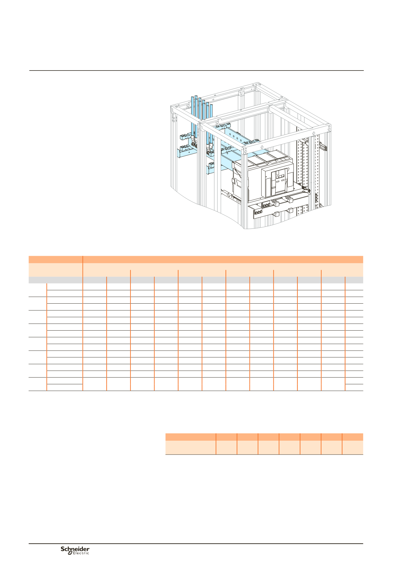
Masterpact NW08 to NW40
Fixed
Vertical mounting
Front or rear connection
Incoming via top or bottom
Busbar drawings supplied by
Schneider Electric
Dd383675.eps
Customer connection
Flat bars, 10 mm thick
Device
Permissible current (A)
Ambient temperature around the switchboard
25 °C
30 °C
35 °C
40°C
45 °C
50 °C
IP
y
31 IP > 31 IP
y
31 IP > 31 IP
y
31 IP > 31 IP
y
31 IP > 31 IP
y
31 IP > 31 IP
y
31 IP > 31
NW08 Size per phase 1b 60 x 10 1b 60 x10 1b 60 x 10 1b 60 x10 1b 60 x 10 1b 60 x10 1b 60 x 10 1b 60 x10 1b 60 x 10 1b 60 x10 1b 60 x 10
bb
I (A)
800
800
800
800
800
800
800
800
800
800
800
NW10 Size per phase 1b 60 x 10 1b 60 x10 1b 60 x 10 1b 60 x10 1b 60 x 10 1b 60 x10 1b 60 x 10 1b 60 x10 1b 60 x 10 1b 60 x10 1b 60 x 10
bb
I (A)
1000
1000
1000
1000
1000
1000
1000
1000
1000
1000
1000
NW12 Size per phase 1b 60 x 10 1b 60 x10 1b 60 x 10 1b 60 x10 1b 60 x 10 1b 60 x10 1b 60 x 10 1b 60 x10 1b 60 x 10 1b 60 x10 1b 60 x 10
bb
I (A)
1250
1250
1250
1250
1250
1250
1250
1250
1250
1250
1250
NW16 Size per phase 1b 80 x 10 1b 80 x 10 1b 80 x 10 1b 80 x 10 1b 80 x 10 1b 80 x 10 1b 80 x 10 1b 80 x 10 1b 80 x 10 1b 80 x 10 1b 80 x 10
bb
I (A)
1600
1600
1600
1570
1600
1520
1570
1470
1520
1420
1470
NW20 Size per phase 2b 80 x 10 2b 80 x 10 2b 80 x 10 2b 80 x 10 2b 80 x 10 2b 80 x 10 2b 80 x 10 2b 80 x 10 2b 80 x 10 2b 80 x 10 2b 80 x 10
bb
I (A)
2000
2000
2000
2000
2000
2000
2000
1950
2000
1900
1950
NW25 Size per phase 2b100 x 10 2b100 x 10 2b100 x 10 2b100 x 10 2b100 x 10 2b100 x 10 2b100 x 10 2b100 x 10 2b100 x 10 2b100 x 10 2b100 x 10
bb
I (A)
2500
2500
2500
2500
2500
2460
2500
2380
2500
2300
2460
NW32 Size per phase 2b120 x 10 2b120 x 10 2b120 x 10 2b120 x 10 2b120 x 10 2b120 x 10 2b120 x 10 2b120 x 10 2b120 x 10 2b120 x 10 2b120 x 10
bb
I (A)
3200
3000
3170
2910
3080
2820
3000
2730
2910
2630
2820
NW40 Size per phase
(2)
(2)
(2)
(2)
(2)
(2)
(2)
(2)
(2)
(2)
(2)
bb
I (A)
(1)
bb
Connection impossible due to the operating-temperature limits of the devices installed in the switchboard.
(1)
For NW40 IP >31, performances realized with forced ventilation.
(2)
Contact Schneider Electric for 4000 A dedicated cubicle
Canalis connection
For Canalis connections, apply the appropriate derating coefficient K.
Device
NW08 NW10 NW12 NW16 NW20 NW25 NW32
Derating
coefficient K
1
1
1
0,98 0,98 0,97 0,97
Note:
the values indicated above have been validated for Prisma P switchboards.
Designingcustomerconnections
Fixed Masterpact NW08 to NW40