


 109 / 413

4/43
Functions specific to the TSX CSY 85 module
(
continued)
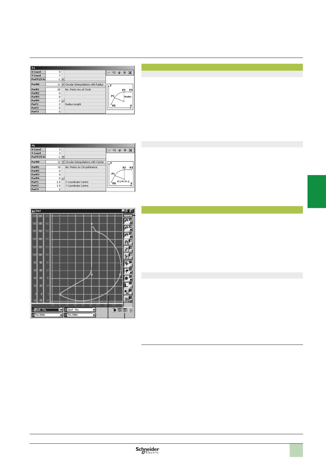
Circular interpolation according to radius
This type of interpolation is used to connect segments via a circular path (arcs) by
specifying start and end points, the radius of the circle and the direction of the path
(
clockwise or counter-clockwise). The specific parameters defining this type of path
are:
b
“
ParW1” indicates the number of points in the arc
b
“
ParW4” defines the direction of the path (clockwise or counter-clockwise)
b
“
ParF1” corresponds to the radius of the arc.
Circular interpolation according to radius:
b
Is only possible for a movement in a single plane (2 axes only)
b
Cannot be used to create paths in a full circle (to do this, use linear interpolation
with circular interpolation connection)
Circular interpolation according to centre
This type of interpolation is also used to connect segments via a circular path (arcs
or full circles) by specifying start and end points, the coordinates of the centre of the
circle and the direction of the path (clockwise or counter-clockwise). The specific
parameters defining this type of path are:
b
“
ParW1” indicates the number of points in the arc
b
“
ParW4” defines the direction of the path (clockwise or counter-clockwise)
b
“
ParF1” indicates the abscissa of the centre of the circle (X)
b
“
ParF2” indicates the ordinate of the centre of the circle (Y)
Full circular movement is defined by an end point which is the same as the start point.
Circular interpolation is only possible for a movement in a single plane (2 axes only).
TjE path editor software
TjE path editor software, supplied with the SERCOS TSX CSY 85 motion control
module, is used in offline mode to:
b
Create master/slave axes and sets of axes for use in paths, with a maximum of 3
sets of 2 real axes or 2 sets of 3 axes
b
Each slave axis requires a cam profile selected from the 7 profiles available in the
TSX CSY 85 module (with a limit of 10,000 cam points for all the profiles)
b
Define paths by setting parameters for each segment, which are linked to the
various possible interpolations described above and on page 4/42
b
The TjE software validates all the parameters and calculates the paths for each
set of axes
Path display
The TjE software integrates various graphic tools for displaying paths that were
previously created and the data relating to the axes (making up these paths) with
their positions, speeds or accelerations. The paths can be displayed with:
b
A choice of curves, colours and scaling
b
A choice of scales and offsets
b
Display of segment reference points
b
Display of points of the master, and calculated points of the cam profiles
This display enables the user to validate the paths before transferring all the data
that has been generated to the PL7 Junior/Pro application managing the SERCOS
TSX CSY 85 motion control modules.
(1)
Maximum, 8 real axes per
TSX CSY 85
module.
Presentation:
page 4/40
Description:
page 4/41
References:
page 4/45
Functions
(
continued)
Modicon Premium automation
platform
SERCOS TSX CSY 84/85/164
motion control modules
2
1
3
4
5
6
7
8
9
10