


 108 / 413

4/42
Functions specific to the TSX CSY 85 module
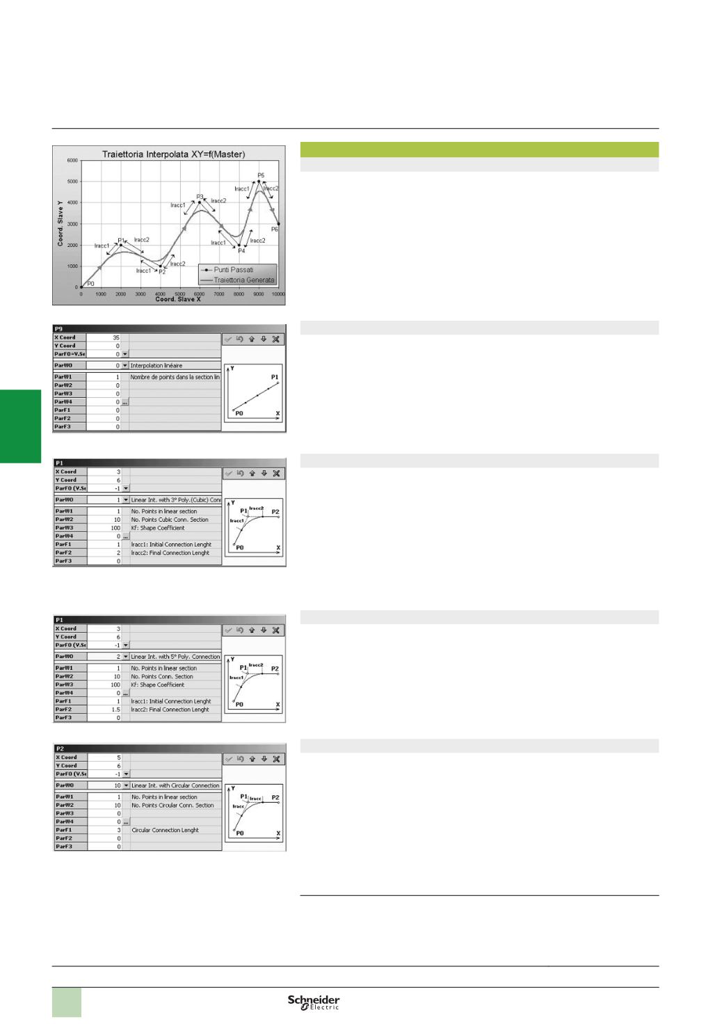
Creation of paths using TjE editor
All paths, whether simple or complex, are divided into linear or circular segments
linked together by interpolation laws (6 possible types). Each segment is
characterized by:
b
X and Y coordinates of the point to be reached (in the example to the left, P6) or
“
tangented” (P1, P2, …P5)
b
Its movement speed, maximum or limited according to setpoint (parameter
“
ParF0”, see screens below):
v
The type of interpolation (parameter “ParW0”, see screens below)
v
The number of points in the linear segment (min. 1 point)
v
The number of points in the cubic interpolation part of the segment
v
Various other parameters, depending on the type of interpolation
Linear interpolation
This type of interpolation is used to generate a rectilinear path between the
preceding point P
i-1
and point Pi defining the segment. The various parameters below
are used as follows:
b
“
ParW1” indicates the number of points in the linear segment. This number of
points represents the number of intermediate points that the TSX CSY 85 motion
control module must calculate to define the path on the segment (minimum 1).
b
“
ParW4” is used to indicate that the movement of a third axis will follow the path
(
here, the linear segment) using tangential mode: positioning according to a constant
angle with the path
(1)
.
Linear interpolation with 3° polynomial interpolation connection
This type of interpolation is used to create a curve between 2 linear segments in
accordance with a 3° interpolation in order to smooth the transitions. The path no
longer passes through the defined point P
i
(
in the example on the left, P1) but follows
a curve defined by the following parameters:
b
“
ParW2” indicates the number of points in the cubic interpolation part (curve)
b
“
ParW3” defines the shape coefficient of the cubic interpolation enabling the curve
to move closer to or further away from the defined point P
i
b
“
Iracc1” and “Iracc2” correspond to the initial and final connection lengths. If these
lengths are too great, maximum lengths are calculated by the TSX CSY 85 motion
control module as a function of the previous section for Iracc1 and of the following
section for Iracc2.
Linear interpolation with 5° polynomial interpolation connection
5
° polynomial interpolation is used to define a path in exactly the same way as with
3
° polynomial interpolation.
However 5° interpolation provides more flexible movement than 3° interpolation.
If the acceleration limit in the segment in question is reached, the speed on this
segment can be reduced for this type of connection.
Linear interpolation with circular interpolation connection
This type of interpolation is used to link segments via a circular path (arcs or full
circles). The specific parameters defining this type of path are:
b
“
ParW2” indicates the number of points in the circular interpolation part
b
“
ParW4” defines whether the arc is greater or less than 180° (defining the direction
of the arc)
b
“
ParF1” corresponds to the length of the circular interpolation segment
Circular interpolation is only possible for a movement in a single plane (2 axes only).
(1)
Available in a later version of the TjE software.
Presentation:
page 4/40
Description:
page 4/41
References:
page 4/45
Functions
Modicon Premium automation
platform
SERCOS TSX CSY 84/85/164
motion control modules
2
1
3
4
5
6
7
8
9
10