


 107 / 413

4/41
Block diagram
(
continued)
The PL7 Junior/Pro or Unity/Pro software is used, via the Premium platform terminal
port, to:
b
Declare SERCOS TSX CSY 84/85/164 modules in the PLC configuration
b
Configure the functions and set the parameters for the axes used
b
Program the movements in the PLC application
b
Adjust the parameters via operating codes (parameters, TSX CSY module and
Lexium servo drive
(1)
with SERCOS option)
b
Test and debug the application
The UniLink software is used, via the RS 232 terminal port on the Lexium servo drive
(1)
(
with SERCOS option), to:
b
Define the types of Lexium servo drive (with SERCOS option) and BDH/BSH
servo motors
b
Adjust the parameters of the Lexium servo drives (with SERCOS option), back
them up in the drives' EEprom memories and archive them on a compatible PC
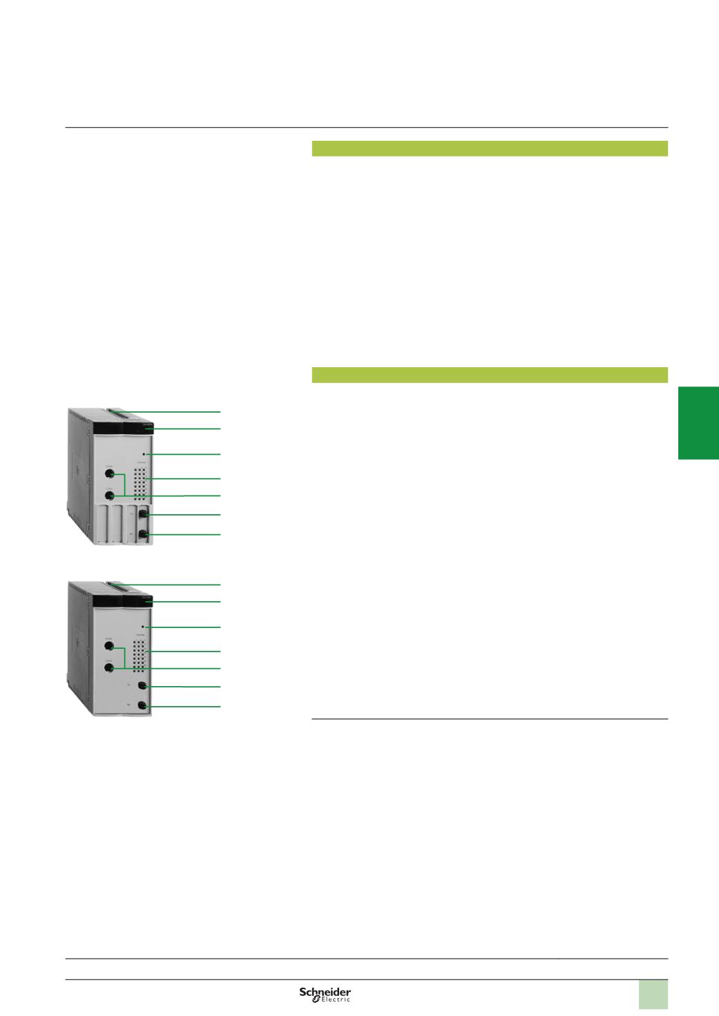
Description
SERCOS TSX CSY 84/85/164 axis control modules comprise:
1
An SMA connector, marked TX, for connecting the servo drives via the fibre optic
cable (SERCOS ring transmission)
2
An SMA connector, marked RX, for connecting the servo drives via the fibre optic
cable (SERCOS ring reception)
3
Double format rigid casing, which:
v
Holds electronic cards
v
Locates and locks the module in its slot
4
Module diagnostic LEDs:
v
RUN LED (green): on, the module is operating correctly
v
SER LED (yellow): flashing, transmission and reception of data on the SERCOS
network
v
ERR LED (red):
-
On, internal module fault
-
Flashing, module start-up, communication fault, incompatible configuration or
application missing
v
I/O LED (red): on, external fault or application fault
v
INI LED (yellow): flashing, module initializing
5
Channel diagnostic LEDs (green): on, axis in normal operation; off, configuration
fault; flashing, serious error on axis:
v
1
to 8: display of 8 real axes
(2)
v
9
to 12: display of 4 imaginary axes
(2)
v
13
to 16: display of 4 remote axes
(2)
v
17
to 20: display of 4 sets of coordinated axes
v
21
to 24: display of 4 sets of follower axes
6
A pencil point button for reinitializing the module
7
Two 8-way mini-DIN connectors reserved for Schneider Electric use
(1)
Please consult our Customer Care Centre.
(2) 1
to 16: display of 16 axes (can be real, imaginary or remote) with the
TSX CSY 164
module.
Presentation:
page 4/40
Functions:
pages 4/42 ...
References:
page 4/45
TSX CSY 84/164
3
4
6
5
7
2
1
TSX CSY 85
3
4
6
5
7
2
1
Description
Modicon Premium automation
platform
SERCOS TSX CSY 84/85/164
motion control modules
2
1
3
4
5
6
7
8
9
10