


 147 / 338

B-13
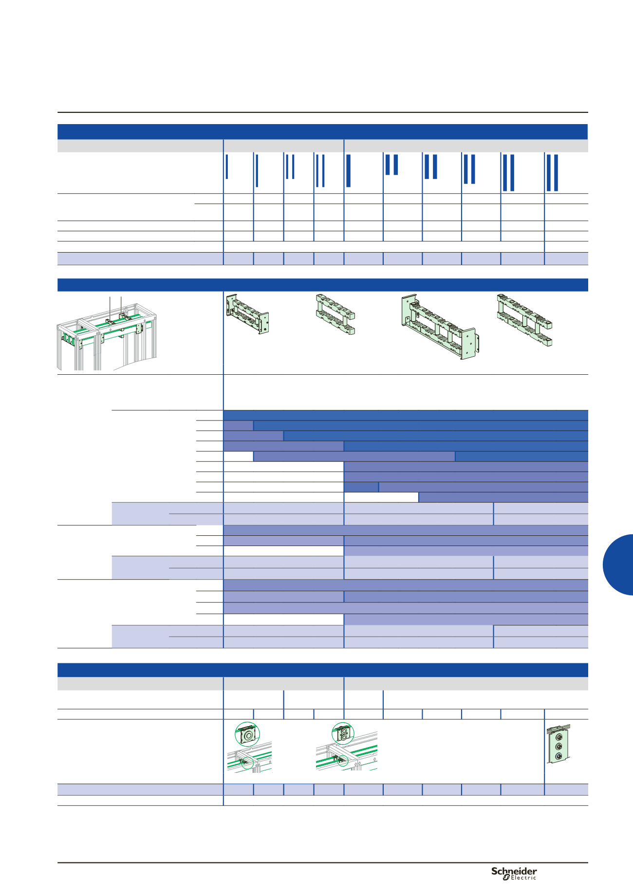
Linergy BS
Horizontal busbars up to 4000 A
400 mm deep installation
Distribution
Power busbars
Flat bars
Installation
Up to 1600 A
Up to 4000 A
Copper without holes, 2000 mm wide
Permissible current for an ambient
temperature of 35 °C around the
switchboard
IP
y
31 800 A 1000 A 1400 A 1800 A 1800 A 2050 A 2300 A 2820 A 3300 A 3760 A
IP > 31 750 A 900 A 1250 A 1600 A 1600 A 1850 A 2000 A 2500 A 2900 A 3340 A
Size of bars (mm)
60 x 5 80 x 5 60 x 5 80 x 5 80 x 10 50 x 10 60 x 10 80 x 10 100 x 10 120 x 10
Number of bars per phase
1
1
2
2
1
2
2
2
2
2
Total number of vertical modules (50 mm)
3
4
Catalogue numbers
04536 04538 04536 04538 04548 04545 04546 04548 04550
04552
Busbar supports
DD381229-LIN-30.eps
DD381226-LIN-15.eps
DD381225-LIN-15.eps
DD385513.eps
DD385514.eps
Fixed support
04664
Free support
04662
Fixed support
04665
Free support
04678
In cubicle
W = 650 or
W = 650+150
busbar
supports
75 mm between
centres
Characteristics
Two fixed supports for 650 mm, 650 + 150 mm wide frameworks and one fixed support for 300/400 mm wide
Prisma P frameworks are mandatory. If more supports are required, use free supports.
Note:
in case of 600 mm depth with 115 mm between centers, replace
04664
fixed support by
04665
and
04662
free support by
04678.
Number of supports
depending on Icw
(kA rms/1 s)
y
15
2
y
25 2+1 2
y
30 2+1
2
y
40 2+1
y
50 -
2+1
2
y
60 -
2+1
y
65 -
2+1
y
75 -
2+2
2+1
y
85 -
-
2+1
Catalogue
numbers
Fixed support
04664
04664
04664
+
04671
(1)
(hardware)
Free support
04662
04662
04662
+
04671
(1)
(hardware)
In duct
W = 300
busbar
supports
75 mm between
centres
Number of supports
depending on Icw
(kA rms/1 s)
y
30 1
y
50 1 + 1
1
y
85 -
1 + 1
Catalogue
numbers
Fixed support
04664
04664
04664
+
04671
(1)
(hardware)
Free support
04662
04662
04662
+
04671
(1)
(hardware)
In duct
W = 400
busbar
supports
75 mm between
centres
Number of supports
depending on Icw
(kA rms/1 s)
y
25 1
y
40 1 + 1
1
y
50 1 + 1
y
85 -
1 + 1
Catalogue
numbers
Fixed support
04664
04664
04664
+
04671
(1)
(hardware)
Free support
04662
04662
04662
+
04671
(1)
(hardware)
(1)
04671
: mounting hardware for bars or profile H = 100 or 120 mm. Comprises 2 threaded rods and 4 insulators.
Joints
Installation
Up to 1600 A
Up to 4000 A
1 bar per phase 2 bars per phase 1 bar per
phase
2 bars per phase
Size of bars (mm)
60 x 5 80 x 5 60 x 5 80 x 5 80 x 10 50 x 10 60 x 10 80 x 10 100 x 10 120 x 10
Sliding joints with torque nut
DD381227-LIN.eps
DD381231-LIN.eps
DD385358.eps
04640
04641
04653
Catalogue numbers (1 joint per phase)
04640 04641 04640 04641 04641 04640 04640 04641 04641
04643
Note
when installed at the bottom of cubicles, the busbars must be partitioned.