


 144 / 338

B-10
DD382327R.eps
Dd382326.eps
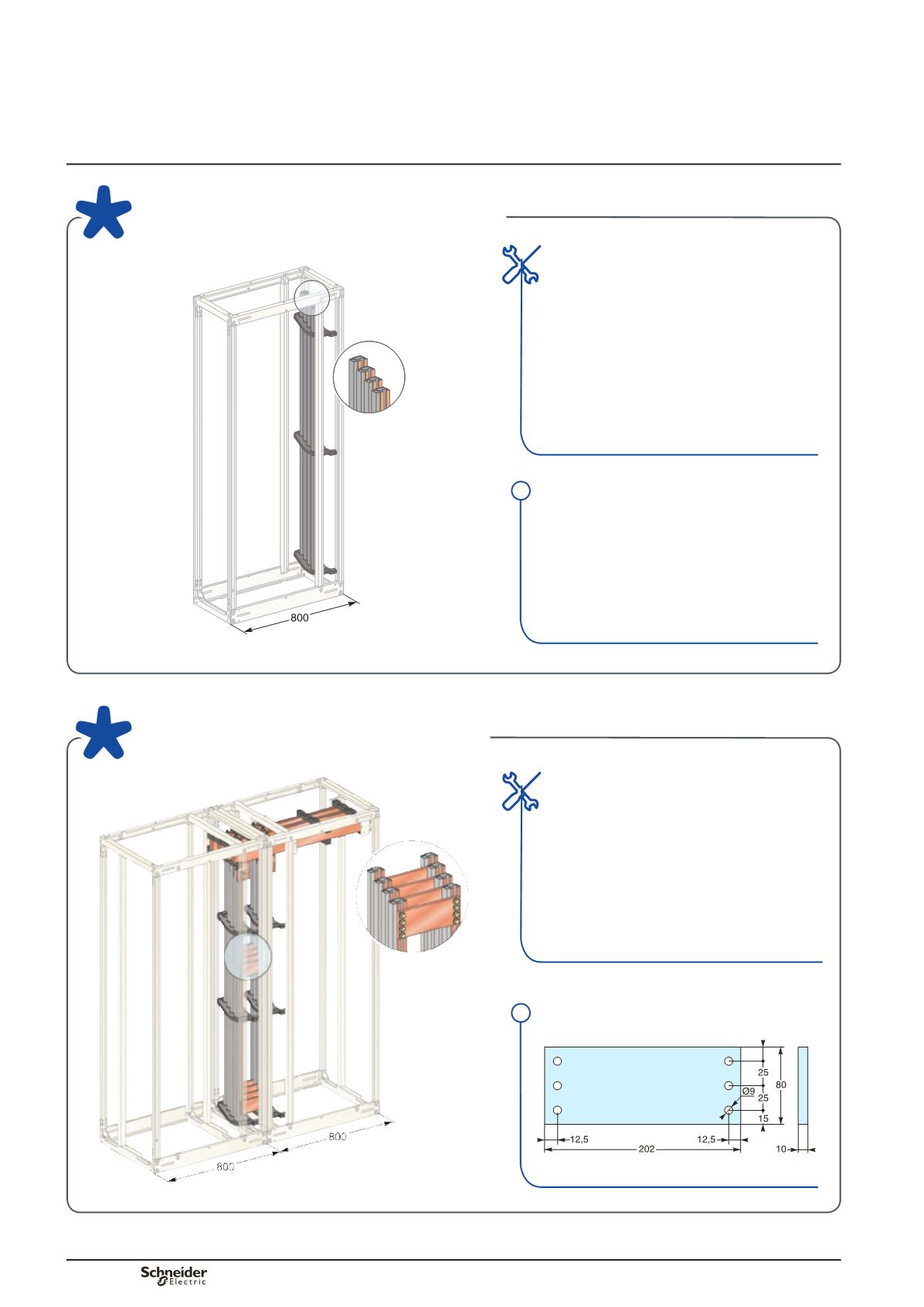
Linergy LGY busbars
presentation
Lateral busbars
Distribution
Main distribution
Linergy LGY busbars from 630 to 1600 A
Linergy LGY busbars up to 3200 A
Installation
>>
Can be installed independently on either
the left or right-hand side of an 800 mm
wide framework (650 + 150 mm) for
distribution on either side.
>>
For an Icw
y
40 kA rms / 1 s, two supports in
the “device” zone are sufficient tomaintain
the bars. A third support is required as the
bottom support for the bars.
Installation
Two sets of busbars are installed in parallel in
two adjacent frameworks, each 800mmwide
(650+150mm).Theymustbeinterconnected
by three equipotential links. Generally
speaking, these links are provided by:
>>
the horizontal busbars
>>
connections in themiddle and at the bottom
of the vertical busbars.
Type of busbar
>>
Very rigid profile to improve withstand to
electrodynamic forces.
>>
Connection points accessible from the
front and adjustable from top to bottom.
>>
Compatible with all Prisma P prefabricated
connections.
Equipotential link
DD382576.eps
Note:
Equipotential link to be made.