


 150 / 338

B-16
Linergy BS
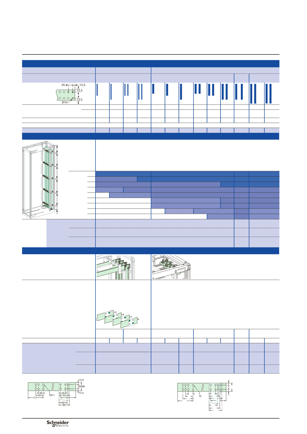
Lateral flat busbars up to 4000 A
400 mm deep installation
Distribution
Power busbars
Flat bars
Up to 1600 A
Up to 4000 A
In duct
W150
W150
2 x
W150
W300
Copper without holes,
1675 mm wide
DD381505-LIN.eps
Permissible current for an ambient
temperature of 35 °C around the
switchboard
IP
y
31 800 A 1000 A 1400 A 1800 A 1200 A 1400 A 1800 A 2050 A 2300 A 2820 A 3200 A 3200 A 3760 A
IP > 31 750 A 900 A 1250 A 1600 A 1080 A 1250 A 1600 A 1850 A 2000 A 2500 A 2820 A 2820 A 3340 A
Size of bars (mm)
60 x 5 80 x 5 60 x 5 80 x 5 50 x 10 60 x 10 80 x 10 50 x 10 60 x 10 80 x 10 80 x 10 100 x 10 120x10
Number of bars per phase
1
2
1
2
Catalogue numbers
04516 04518 04516 04518 04525 04526 04528 04525 04526 04528 04528 04550 04552
Busbar supports
IL[H
IL[H
FDODJH
YRODQW
YRODQW
PP
PD[L
PP
PD[L
PP
PD[L
PP
PD[L
PP
PD[L
PP
PD[L
IL[H
DD380724A.eps
Description Attach directly to the framework.
Three fixed supports are required to maintain the busbars. If more than three supports are required, use additional
free supports.
The bottom support maintains the bars in position.
It is not considered a busbar support.
Note
:
In case of 600 mm depth with 115 mm between centers, replace
04661
fixed support by
04668
and
04662
free support by
04678
and
04663
or
04666
bottom support by
04673
.
Number of
supports
depending
on Icw
(kA rms/1 s)
y
15 3
3
2 x 3
y
25 3+2
3
3
2 x 3
y
30 3+2
3+2
3
2 x 3
y
40 3+4
3+2
3+2
2 x 3
y
50 -
3+4
3+2
2 x 3
y
60 -
3+4
3+2 2 x 3+2
y
65 -
3+4
3+2 2 x 3+2
y
75 -
-
3+6
3+4
2 x 3+2
y
85 -
-
3+4
2 x 3+2
In duct
W150, W = 300
busbar
supports
75 mm
between
centres
Catalogue
numbers
Fixed support
04661
2 x
04661
04661
+
04671
Free support
04662
2 x
04662
04662
+
04671
Bottom support
04663
2 x
04663
04666
+
04661
Connections to the horizontal Linergy BS busbars
DD383844_R.eps
DD385418.eps
Characteristics
For busbars with 75 mm between
centres, the bars must fully
overlap.
To satisfy safety clearances, the
assembly points on adjacent
bars must be staggered as shown
above.
(1)
Catalogue numbers
04636
and
04637
include 1 connection only.
Order 1 connection per phase.
Reference
04642
consists of 2 M8 x 140 screws which can replace the original
M8 x 120 screws.
DD383399_R-LIN.eps
1 bar per phase 2 bars per
phase
1 bar per phase
2 bars per phase
double
BB
2 bars per phase
Size of vertical bars (mm)
60 x 5 80 x 5 60 x 5 80 x 5 50 x 10 60 x 10 80 x 10 50 x 10 60 x 10 80 x 10 80 x 10 100 x 10 120 x 10
Catalogue number of the
connecting part according to
the size of the horizontal bars
y
80 mm
04645
(2)
04636
04637 04637
2x
04637
04645
(2)
04645
(2)
100 mm
04645
(2)
04636
+
04642 04637
+
04642
04637
+
04642
04637
+ 2 x
04642
04645
(2)
04645
(2)
120 mm
04645
(2)
04648
04648 04648
2x
04648
04645
(2)
04645
(2)
(1)
Drilling diagram for horizontal busbars, 5 mm thick.
Drilling diagram for horizontal busbars, 10 mm thick.
DD383398-LIN.eps
50/60/80/100
111
12,5
12,5
100
80
60
111
75
55
35
11
75
55
35
DD384320-LIN.eps
(2)
Sides screws.
Note:
for more information, see page D-86.