


 483 / 759

483
WIRING DEVICES
Technical Hotline
+44 (0)1268 563720
For a full range of corresponding products,
see pages 98-128 in the product selector.
Aspect Installation
Wiring Devices Technical
– Aspect
The MK ‘Aspect’ range of products consists of the main product
complete with its support frame and clipping medium, plus a
separate frontplate. The product is mounted to the wall, after
wiring, and the front plate clipped onto the frame.
1.
The frontplate is supplied loose to aid installation.
2.
Make sure not to crush or deform the spring steel clips situated
along one edge of the product support frame.
3.
A gasket is also supplied with each product, which may prove
useful on uneven walls. See note 5 below.
4.
Using the gasket with all switches and the German socket, will
ensure full compliance with the appropriate standards.
5.
Both standards set out to guarantee full engagement of the
frontplate on uneven surfaces, even when there is a mismatch
of as much as 1mm between the distance the main body of the
product is from the wall and that of the front plate.
6.
Where no gasket is used, if thick wallpapers are cut such that
they fit around the support frame and therefore remain under
the edge of the frontplate, full plate engagement with the clips
may be restricted.
Note:
When installing Aspect do not over tighten screws, so as to prevent
damage or distortion to the product or support frame.
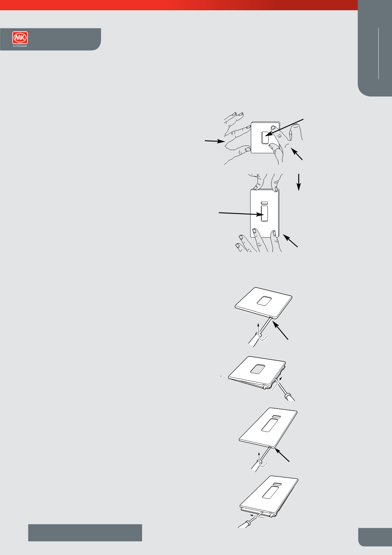
Frontplate Removal
1.
Turn off the power supply.
2.
Carefully slide a screwdriver between the ramp on the main
body of the product and the notch in the lower right hand edge
of the plate.
3.
On uneven walls, make sure the screwdriver does not go
between the spring steel ramp and the wall, or damage to the
wall and/or product could result.
4.
Carefully slide the blade upwards and then gently lift the
handle away from the wall, which will lever the plate away from
the first clip. See Fig.4.
5.
With the first clip released, support the plate with one hand and
continue to move the blade to the left under.
Data products in euromounting frames
Products operating at extra low voltage levels (<50v) must not
be mounted in the same Euro enclosures as equipment rated in
excess of 50v.
Cleaning Frontplates
In order to protect the quality surface finish of the front plate,
periodic cleaning should only consist of polishing with a dry lint
free soft cloth.
Figure 1a
Adjust
North/South
to align with
plate aperture
Apply a force
in this
direction
Force applied
towards the
wall
Figure 1b
Adjust
North/South to
align with plate
aperture
Apply a
force in this
direction
Force applied
towards the
wall
Gently lever
away from
wall
Blade to be
between notch in
plate and ramp on
support frame
Figure 2
Figure 3
Slide screwdriver
up to disengage
other clip
Gently lever
away from
wall
Blade to be
between notch in
Figure 4
Figure 1a
Adjust
North/South
to align with
plate aperture
Apply a force
in this
direction
Force applied
towards the
wall
Figure 1b
Adjust
North/South to
align with plate
aperture
Apply a
force in this
direction
Force applied
towards the
wall
Gently lever
away from
wall
Blade to be
between notch in
plate and ramp on
support frame
Figure 2
Figure 3
Slide screwdriver
up to disengage
other clip
Gently lever
away from
wall
Blade to be
between notch in
plate and ramp on
support frame
Figure 4
i re
A just
Nort / out
t ali n it
lat a ert r
pply f rce
i t is
direction
F rce
li
t w rds t e
all
i ur 1b
j st
rt /
t to
align ith plate
aperture
Apply a
force in this
direction
orce applied
to ards the
all
tly l v r
y fr
ll
l de to be
et e tch i
l te an r
su ort fr
ig r 2
i r
li
scr
riv r
t is
t r cli
tly l v r
y fr
ll
l
t
t
tc i
plate and ramp on
support frame
i r
Figure 1a
Adjust
North/South
to align with
plate aperture
Apply a force
in this
direction
Force applied
towards the
wall
Figure 1b
Adjust
North/South to
align with plate
aperture
Apply a
force in this
direction
Force applied
towards the
wall
Gently lever
away from
wall
Blade to be
between notch in
plate and ramp on
support frame
Figure 2
Figure 3
Slide screwdriver
up to disengage
other clip
Gently lever
away from
wall
Blade to be
between notch in
plate and ramp on
support frame
Figure 4
Figure 5
Figure 1a
Adjust
North/South
to align with
plate aperture
Apply a force
in this
direction
Force applied
towards the
wall
Figure 1b
Adjust
North/South to
align with plate
aperture
App y a
forc in this
direction
Force applied
towards the
wall
Gently lever
away from
wall
Blade to be
between notch in
plate and ramp on
support frame
Figure 2
Figure 3
Slide screwdriver
up to disengage
other clip
Gently lever
away from
wall
Blade to be
between notch in
plate and ramp on
support frame
Figure 4
Slide screwdriver
to the left to
disengage other clip
Figure 5
to align with
plate aperture
Apply a force
in this
direction
Force applied
towards the
wall
Figure 1b
Adj st
North/South to
align with plate
aperture
Apply a
forc in this
direction
Forc plied
towards the
wall
Gently lever
away from
wall
Blade to be
between notch in
plate and ramp on
support frame
Figure 2
3
Slide screwdriver
up to disengage
other clip
Gently lever
away from
wall
Blade to be
between notch in
plate and ramp on
support frame
Figure 4
Slide screwdriver
to the left to
disengage other clip
Figure 5
FIGURE 1A
FIGURE 2
FIGURE 3
FIGURE 4
FIGURE 5
FIGURE 1B
Frontplate Installation
Frontplate Removal