


 489 / 759

Technical Hotline
+44 (0)1268 563720
489
FEATURES
Battenfit Switching
PIR Sensor
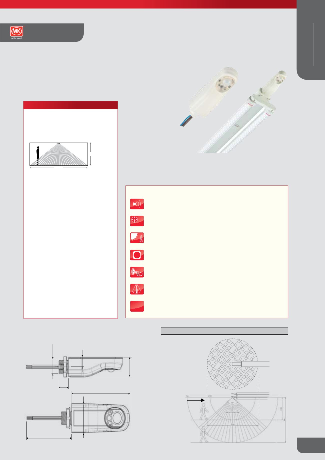
Description
Ideal for retrofit installations, the BattenFit sensor is a simple-to-fit control
solution for batten style luminaires which can deliver energy savings of up
to 70%
K4047
14
M20 x 1.5
29
14
107
102
600
40
Selectable Options
(Factory pre-set shown in bold)
On
/ Off
Auto
/ Semi-Auto
1 min-96 hrs plus 10-second walk test.
20 mins
Off
/ On
Max
/ Min
Select Scenes 1 - 6.
Scene 1
Yes /
No
Reg 100-50% Sets the regulating range of the ballast in daylight
conditions, i.e. at 100% the ballast can regulate over its full range,
at 70% the ballast will not dim below 30% output.
Reg 100%
10-100% (10-50% in 5% increments; 50%+ in10% increments)
100%
Yes /
No
Switch off after Off Delay
Go to Minimum and do not switch off
Go to Minimum for 3 x Off Delay (XTN), then switch off
Regulate up to 25% and do not switch off
Go to Scene 6
for 3 x Off Delay (XTN)
Passive
/ Active / Disabled
0-254 Point where photocell turns lights on in Active Mode
254
0-254 Point where photocell turns lights off in Active Mode
254
These parameters may be re-programmed any number of times
and all settings will be retained in the event of a power loss.
MSB1000PT
MSB1000T
MSB1000DT/
MSB1000DALIT
OR
Parameters are fixed at defatults
Technical Data
OPERATING VOLTAGE: 230V~ 50Hz (UK & Europe)
POWER CONSUMPTION: <0.5W
F
F
F
m
2.5m
etectors
onnected
el, as is
bove, to
the same
um Load
SUPPLY
L N E
BALLAST
BALLAST
BALLAST
BALLAST
Do not connect the
Dimming Signal Pair
of one detector to that
of another detector.
L N E
L N E
D D
D D
D D
D D
See ‘Technical Data’ for maximum number of ballasts
MSB1000DT/MSB1000DALIT
L N E
L N E
White
Blue
Brown - Live (L)
- Neutral (N)
Polarity-free (D)
digital output (D)
White
Black
Blue
Brown- Live (L)
- Neutral (N)
- Switched live (L
SW
)
Polarising Plate (not supplied)
Apolarising plate can be made in order to prevent rotation of
the sensor during transport or installation. Please refer to
installation instructions for details on how to produce.
M20 x 1.5
102
600
Selectable Option
On
/ Off
Auto
/ Semi-Auto
1 min-96 hrs plus 10-s
Off
/ On
Max
/ Min
Select Scenes 1 - 6.
Yes /
No
Reg 100-50% Sets th
conditions, i.e. at 100
at 70% the ballast will
10-100% (10-50% in 5
Yes /
No
Switch off after Off D
Go to Minimum and d
Go to Minimum for 3 x
Regulate up to 25%
Go to Scene 6
Passive
/ Active / Dis
0-254 Point where ph
0-254 Point where ph
Programmable
Parameters
Power up
Response
Off Delay
24 Hour Cycle
Start Lamps
Entry Scene
Bright-out
Dimming
Lamp Max
Fade to Off
When Vacant
Photocell Mode
Lower Threshold
Upper Threshold
These parameters m
and all settings will
MSB1000PT
MSB1000T
MSB1000DT/
MSB1000DALIT
Parameters are fixed at defatults
Assembly/Installation
Electrical Connections
Detection Profile
Technical Data
OPERATING VOLTAG
POWER CONSUMPTI
CAPACITY: MSB1000
MSB1000
MSB1000
WEIGHT: 100g
COLOUR: White
MATERIAL: Flame reta
IP RATING: 4X - estim
F
F
F
Ex-Or operates a genuine policy of continuous improvement. You may expect the specification to be regularly enhanced. For lates
Plan View
o
Detection pattern is a 360
cone shape. Diameter is
2.25 x the mounting height.
The squares show the
arrangement of the detection
pattern. Sensitivity is greater
when approaching at a
tangent rather than heading
towards the centre.
Direction of most
commonly used
entry into detection
zone, i.e. start of
corridor or doorway
5m
5m
2.5m
o
97
2.5m
DETECTION ZONE
5.6m
BATTEN LUMINAIRE
LOAD
Multiple Detectors
may be connected
in parallel, as is
shown above, to
control the same
Maximum Load
L N E
Maximum Total Load not to exceed
that specified for a Single Detector
LOAD
LOAD
L N E
L N E
L N E
BALLA
L
D D
See ‘T
MSB1000T/MSB1000PT
MSB1000DT/MSB1000DA
White
Blue
Brown - Live (L)
- Neutral (N)
Polarity-free (D)
digital output (D)
White
Note: If there is insufficient
space for the locknut, an
adaptor (not supplied) can
be used. See installation
instructions for details.
SENSOR
OPTIONAL
POLARISING
PLATE
LIGHT
FITTING
LOCKNUT
L
SW
Dimensions (mm)
TECHNICAL SPECIFICATION
MAXIMUM RECOMMENDED MOUNTING HEIGHT
5.0m
RANGE
Cone-shaped detection pattern,
diameter (at floor level) = 2.4 x mounting height
6.0m
2.5m
OFF DELAY
1 minute – 40mins
10 second walk test mode
PHOTOCELL
Adjustable 50-5000 lux
OPERATING VOLTAGE
230V 50Hz
RECOMMENDED CIRCUIT PROTECTION
10 Amps
MAXIMUM LOAD
2A
COLOUR
White
MATERIAL
Flame retardant PC/ABS
WEIGHT
100g
IP RATING
IP65
ACCESSORIES
K4098 Infrared programming tool required to adjust
sensor settings
Advanced presence detection by passive infrared (PIR) technology
5-35
Off delay in hours following the last observed movement after which
lights switch off
A
Passive photocell holds lights off in bright ambient conditions.
Active photocell has the capability to switch lights off in occupied areas
5m
Detection pattern and range in meters under normal operating
conditions
One Switch Manual input to turn luminaires on or off
Infrared programming enables easy commissioning and
re-commissioning via K4058
IP
IP65
Sensors Technical
WIRING DEVICES
WHITE