


 79 / 140

CI insulated enclosures
Modular busbar system
2010
CA08103002Z-EN
www.eaton.com20/75
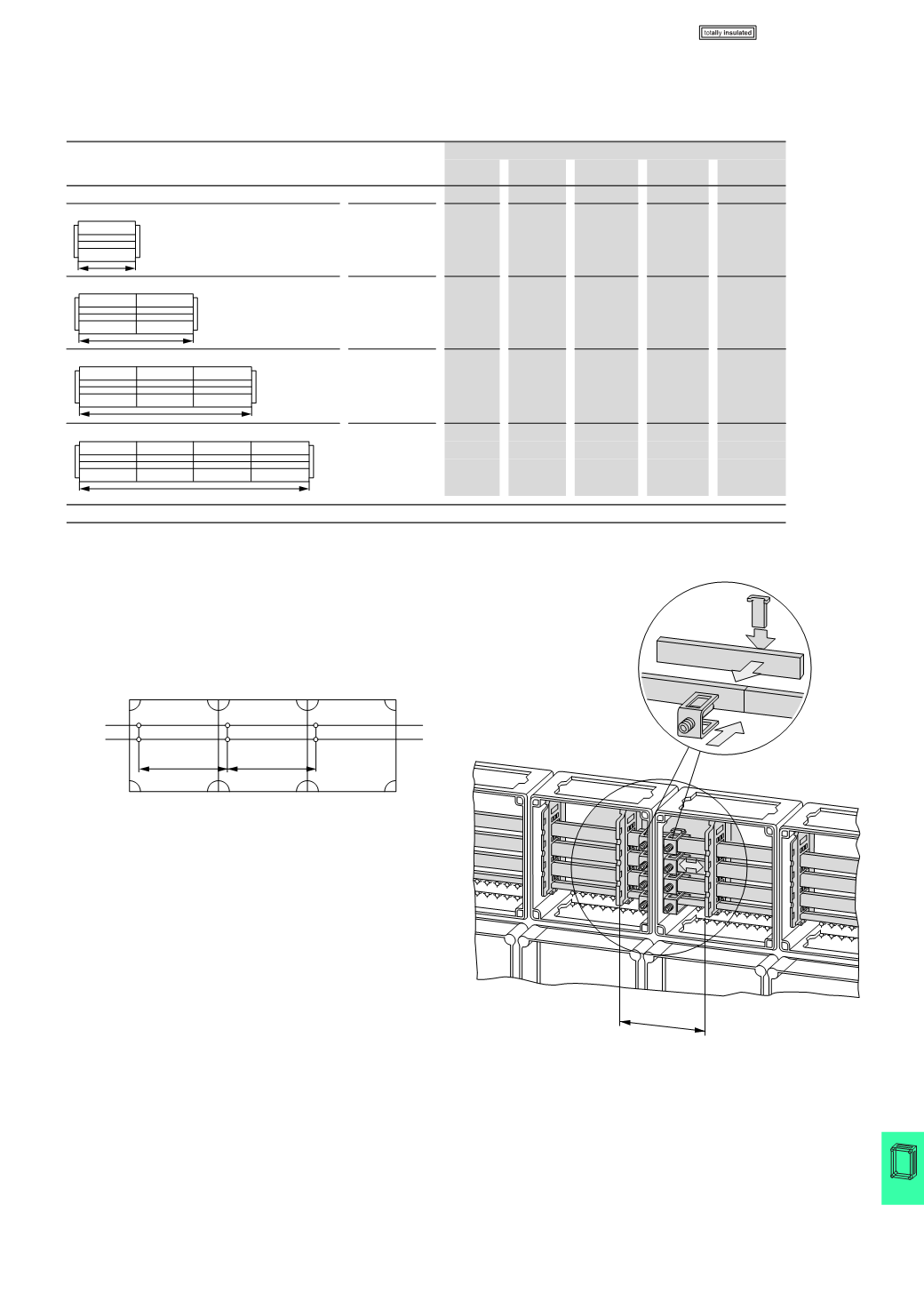
N, PE, PEN at 1600 A
In the 1600 A busbar system, two CU20X15 are each used as N, PE and PEN
conductor. For an even current load, connect the busbars in parallel with a spacing
of no more than 375 mm.
Transport split, busbar connection
With transport splits the busbar supports are offset from the knockouts to the
enclosure inner and secured with an additional holder.
This reduces the mounting area for components fitted on the busbars by distance 'a'
between the busbar supports.
In end enclosures, transport splits should always be fitted to facilitate subsequent
expansion.
Selection diagrams up to 1600 A
3
pole
Busbar system in CI enclosure:
Assembled from individual components
for 1 up to 4 CI enclosures
Operating
current
A
Part no.
CI44-200 SH1603/4 CU40X10
1)
FL4-X
BS4-CI
1600
1
2
3.375
2
-
1600
2
3
6.75
2
1
1600
3
4
10.125
2
2
1600
4
5
13.50
2
3
Notes
1)
In meters; applies for 5-pole system
To achieve even current loading (and heating) of the individual busbars, they must be connected in parallel with busbar terminals at a maximum
spacing of 375 mm. Incoming and outgoing terminals are parallel switching points.
L1
L2
L3
375
L1
L2
L3
750
L1
L2
L3
1175
L1
L2
L3
1500
N, PE, PEN
375
375
a
CI..., SKA...