


 77 / 140

CI insulated enclosures
Modular busbar system
2010
CA08103002Z-EN
www.eaton.com20/73
Modularbusbar system
Overview of busbar systems up to 1600 A (CI…, RS…, SKA…)
• 5-
conductor system up to 400 A with 1/1 cross-section possible
• 5-
conductor system up to 630 A L1 - L3 with 1/1 cross-section,
PE/N with 1/2 cross-section
• 25
A to 400 A fuses for mounting on busbar system up to 630 A
•
Tinned copper busbars from 160 A to 630 A
Rated
operational current I
e
Busbar cross-section
Busbar center-to-
center distance
Surface-mounting devices
A
L1, L2, L3 mm PE, N, PEN mm mm
RS..3-50 GST…00 GSTA…
160
12
x 5
12
x 5
40
-
● -
250
20
x 5
20
x 5
50
● ● ●
400
20
x 10
20
x 5
50
● ● ●
630
20
x 15
20
x 10
50
● ● ●
1000
2
x 30 x 10
30
x 10
-
-
-
-
1600
3
x 40 x 10
2
x 20x15
-
-
-
-
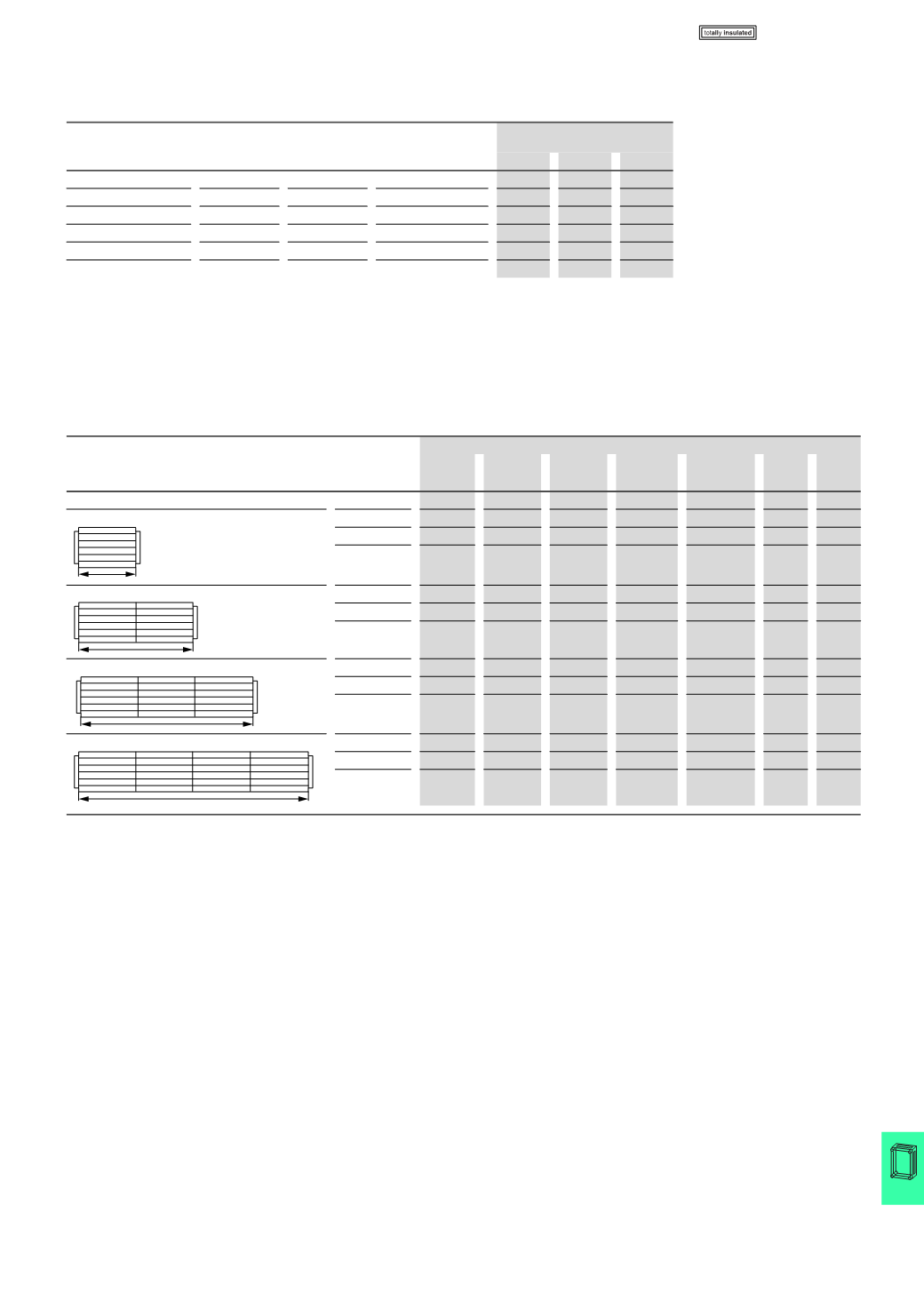
Selection diagrams up to 630 A
up to 5-pole (with or without fitted components)
(
CI…, SKA…)
Busbar system in CI enclosure:
Assembled from individual components
for 1 up to 4 CI enclosures
Rated
operational
current
A
Part no.
CI44-200 SH0635/4 CU20X5
1)
CU20X10
1)
CU20X15
1)2)
FL4-X BS4-CI
250
1
2
1.875
-
-
2
-
400
1
2
0.75
1.125
-
2
-
630
1
2
-
0.75
1.125
2
-
250
2
3
3.75
-
-
2
1
400
2
3
1.50
2.25
-
2
1
630
2
3
-
1.50
2.25
2
1
250
3
4
5.625
-
-
2
2
400
3
4
2.25
3.375
-
2
2
630
3
4
-
2.25
3.375
2
2
250
4
5
7.50
-
-
2
3
400
4
5
3.00
4.50
-
2
3
630
4
5
-
3.00
4.50
2
3
Notes
1)
In meters; applies for 5-pole system
2)
Assemble from CU20X10 and CU20X5
N
L1
L2
L3
PE
375
N
L1
L2
L3
PE
750
N
L1
L2
L3
PE
1175
N
L1
L2
L3
PE
1500
CI..., RS..., SKA...