


 78 / 140

20/74
CI insulated enclosures
Modular busbar system
2010
CA08103002Z-EN
www.eaton.com3-
pole with fitted components
(5-
pole without fitted components possible)
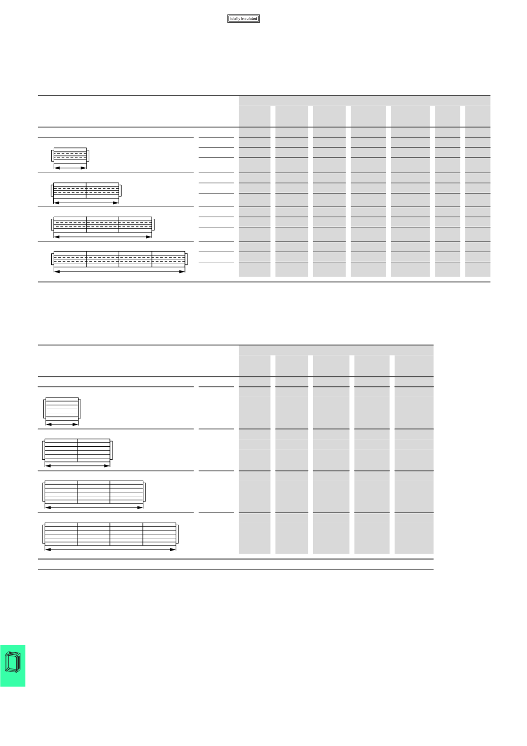
630
A-system max. 3 pole
(
CI…, SKA…)
Busbar system in CI enclosure:
Assembled from individual components
for 1 up to 4 CI enclosures
Rated
operational
current
A
Part no.
CI43-200 SH0635/3 CU20X5
1)
CU20X10
1)
CU20X15
1)2)
FL4-X BS4-CI
250
1
2
1.875
-
-
2
-
400
1
2
0.75
1.125
-
2
-
630
1
2
-
-
1.125
2
-
250
2
3
3.75
-
-
2
1
400
2
3
1.50
2.25
-
2
1
630
2
3
-
-
2.25
2
1
250
3
4
5.625
-
-
2
2
400
3
4
2.25
3.375
-
2
2
630
3
4
-
-
3.375
2
2
250
4
5
7.50
-
-
2
3
400
4
5
3.00
4.50
-
2
3
630
4
5
-
-
4.50
2
3
Notes
1)
In meters; applies for 5-pole system
2)
Assemble from CU20X10 and CU20X5 → 630 A system 3-pole only
L1
L2
L3
N
PE/N
375
L1
L2
L3
N
PE/N
750
L1
L2
L3
N
PE/N
1175
L1
L2
L3
N
PE/N
1500
Selection diagrams up to 1000 A
up to 5 pole
(
CI…, SKA…)
Busbar system in CI enclosure:
Assembled from individual components
for 1 up to 4 CI enclosures
Rated
operational
current
A
Part no.
CI44-200 SH1005/4 CU30X10
1)
FL4-X
BS4-CI
)
1000
1
2
3.00
2
-
1000
2
3
6.00
2
1
1000
3
4
9.00
2
2
1000
4
5
12.00
2
3
Notes
1)
In meters; applies for 5-pole system
To achieve even current loading (and heating) of the individual busbars, they must be connected in parallel with busbar terminals at a
maximum spacing of 375 mm. Incoming and outgoing terminals are parallel switching points.
N
L1
L2
L3
375
N
L1
L2
L3
750
N
L1
L2
L3
1175
N
L1
L2
L3
1500
CI..., SKA...