


 262 / 413

5/128
Presentation
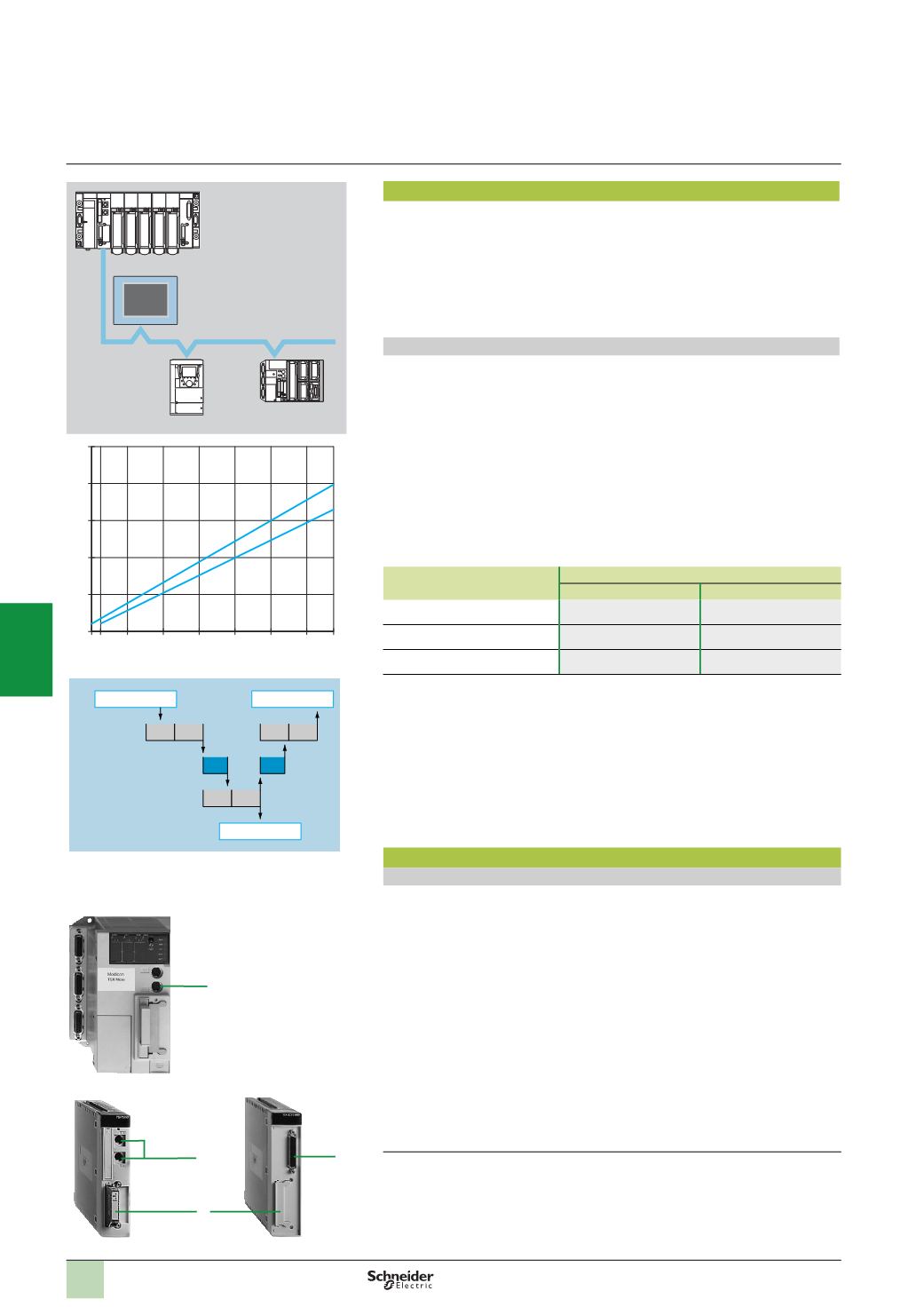
The Uni-Telway bus is a standard means of communication between control system
components (PLCs, MMI terminals, supervisors, variable speed drives, numerical
controllers, weighing equipment, etc.).
It is suitable for architectures designed to manage control and monitoring devices via
a PLC, or architectures used for MMI (supervision, etc.).
The Uni-Telway bus requires a master station which manages the allocation of bus
access rights to the various connected stations (known as slave stations).
Performance
The Uni-Telway bus cycle time depends on:
b
The number of devices polled (datalink addresses)
b
The data rate
b
The turnaround time of each device
b
The number, length and type of messages
BCT
= Bus Cycle Time, is the interval between two polls from the same device.
The curves opposite give the Uni-Telway cycle time as a function of the number of
slaves operating at 9.6 Kbps or 19.2 Kbps, with a typical device turnaround time of
5
ms (without messages).
The following table shows the time to be added (in ms) to obtain the true BCT value
as a function of the traffic (N = Number of usable characters):
Exchanges
Time
(
ms)
at 9.6 kbps
at 19.2 kbps
Master to slave
24
+ 1.2 N
(1)
17
+ 0.6 N
(1)
Slave to master
19
+ 1.2 N
(1)
12
+ 0.6 N
(1)
Slave to slave
44
+ 2.3 N
(1)
29
+ 1.15 N
(1)
In a distributed control system architecture the application-to-application response
time depends not only on the communication system, but also on:
b
The processing times of the message source and destination devices.
b
The degree of asynchronism between the bus and processor cycle times.
The response time must be evaluated by the designer of each application according
to the devices which are connected.
The processing time of a device may vary from one to two cycle times depending on
the degree of asynchronous operation.
Description
Modicon TSX Micro/Premium PLCs
Modicon TSXMicro/PremiumPLCs provide various ways of connecting to the
Uni-Telway bus:
1
By Modicon TSX Micro/Premium processor integrated port
The AUX port
(2)
(8-
way mini-DIN) has one non-isolated RS 485 serial link
channel (maximum distance 10 m).
2
By TSX SCY 21601 integrated port for Modicon Premium PLC
This module has one Half-duplex isolated RS 485 serial link channel, which is
multiprotocol, including Uni-Telway.
3
Via a multiprotocol PCMCIA card
A slot on TSX 37 21/22/Premium processors and on the
TSX SCY 21601
(3)
module accepts the following multiprotocol cards:
-
PCMCIA
TSX SCP 114 card:
isolated RS 485/RS 422 link. This type of card
corresponds to the Uni-Telway standard.
-
PCMCIA
TSX SCP 111 card:
non isolated RS 232 link. This type of card can be
used for direct point-to-point links or links via Modem.
-
PCMCIA
TSX SCP 112
card: 20 mA current loop link. This type of card is used
for a multidrop link (2 to 16 devices) and requires a 24 V
c
external power supply.
(1)
N = Number of usable characters corresponding to the messages to be exchanged.
(2)
TER port for
TSX 37-05/08/10
PLCS, TER or AUX port for Premium PLCs.
(3)
This slot can also take the
TSX FPP 20
PCMCIA card for Fipway networks.
Presentation,
description
Event
Report
CT1 CT1
CT1 CT1
CT2 CT2
Action
Device 1
Device 2
BCT
BCT
Uni-Telway bus
BCT = Uni-Telway bus cycle time
CT1 = Device 1 bus cycle time
CT2 = Device 2 bus cycle time
Modicon TSX Micro
1
2
3
TSX SCY 21601
Modicon Premium
1 4
8
12
16
20
24 27
100
200
300
400
1
2
BCT
(
ms)
1
= 9.6 Kbps
2
= 19.2 Kbps
Magelis XBT G
p
ModiconTSX Micro
Altivar 71/61
Modicon
Premium
Uni-Telway
1
Modicon Premium automation
platform
0
Uni-Telway serial link
2
1
3
4
5
6
7
8
9
10