


 119 / 413

4/53
Description
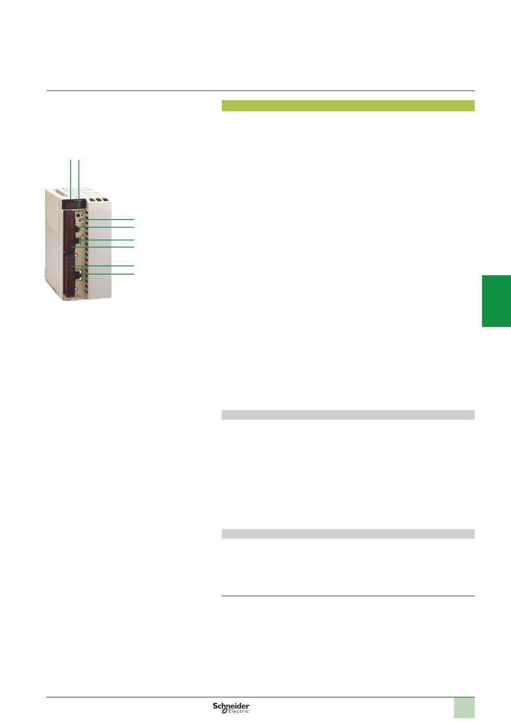
TSX H57 24M/44M Hot Standby processors
Double format Premium Hot Standby
TSX H57 24M
and
TSX H57 44M
processor front panels comprise:
1
A display block with 6 LEDs:
b
RUN LED (green):
v
On steady: processor in Primary mode during operation (program execution)
v
Flashing 2.5 s (on)/0.5 s (off): processor in Standby mode during operation
(
execution of first program section)
v
Flashing 0.5 s (on)/2.5 s (off): processor not in Standby mode
v
Flashing 0.5 s (on)/0.5 s (off): PLC stopped
b
ERR LED (red):
v
On steady: processor or embedded equipment fault (PCMCIAmemory card)
v
Flashing 0.5 s (on)/0.5 s (off): application fault
b
TER LED (yellow): activity on the TER/AUX terminal port
b
I/O LED (red): On steady: fault from another PLC station module or configuration fault
b
STS LED (yellow):
v
Flashing 0.5 s (on)/0.5 s (off): standby mode between the Primary and Standby
processors correct
v
On steady: standby mode inactive or being initialized
v
Off: failure of processor self-tests
b
ACT LED (yellow): activity on the CPU Sync link between the Primary and
Standby processors correct
This standby mode diagnostics is complemented by the 3 LEDs (RUN, ERR and
STS) of the
TSX ETY 4103/5103
communication modules managing the shared I/O
on Ethernet Modbus/TCP.
2
AMemory Extract button: not operational on the Hot Standby processors
3
ARESET button triggering a cold start of the PLC when pressed
4
An 8-way female mini-DIN connector marked TER/AUX for connecting a
programming, adjustment or operator interface terminal
5
AUSB connector marked TER for connecting a programming terminal (requires
the PC-compatible 3.3 m
UNY XCA USB 033
connection cable, to be ordered
separately)
6
A PCMCIA slot (no. 0) for a memory expansion card
7
A PCMCIA slot (no. 1) for a memory expansion card for storing additional data
(1)
8
An RJ45 connector marked HSBY Link dedicated to Hot Standby communication
between the Primary and Standby processors
CPU Sync link
The CPU Sync link
8
marked HSBY Link on the front panel of Hot Standby
processors is a 10BASE-T/100BASE-TX Modbus/TCP Ethernet port dedicated to
exchanges between the Hot Standby System Primary and Standby PLCs.
This link allows the Primary active PLC (as seen by the system I/O) to exchange its
context (status of its data) with the Standby PLC each application cycle, so that if
there is a changeover on failure of the Primary PLC, the Standby PLC can take
control of the control system in 1.5 processor cycles.
The CPU Sync link is a copper link, maximum length 100 m.
d
The use of active components (transceivers, switches, etc.) on the CPU Sync
link is strictly prohibited.
USB terminal port
The USB terminal port
5
with a useful data rate of 12 Mbps is compatible with Unity
Pro programming software and the OPS data server (OPC Factory Server).
TSX H57 24M/44M
processors can be connected to a USB bus comprising several
peripherals, however:
b
Only one processor must be connected to the USB bus
b
No device on the USB bus (modem, printer) can be controlled by the PLC
(1)
The PCMCIA communication cards
TSX SCP 11
p
(
Modbus, Uni-Telway, serial link)
TSX CPP
110
(
CANopen),
TSX FPP 20
(
Fipway) and
TSX MBP 100
(
Modbus Plus) cannot be placed in
slot no. 1 of the Hot Standby processors.
1 2
3
4
5
6
8
7
TSX H57 24M/44M
Modicon Premium automation
platform
0
Hot Standby system
Unity Pro software
2
1
3
4
5
6
7
8
9
10