


 121 / 413

4/55
Architectures
(
continued)
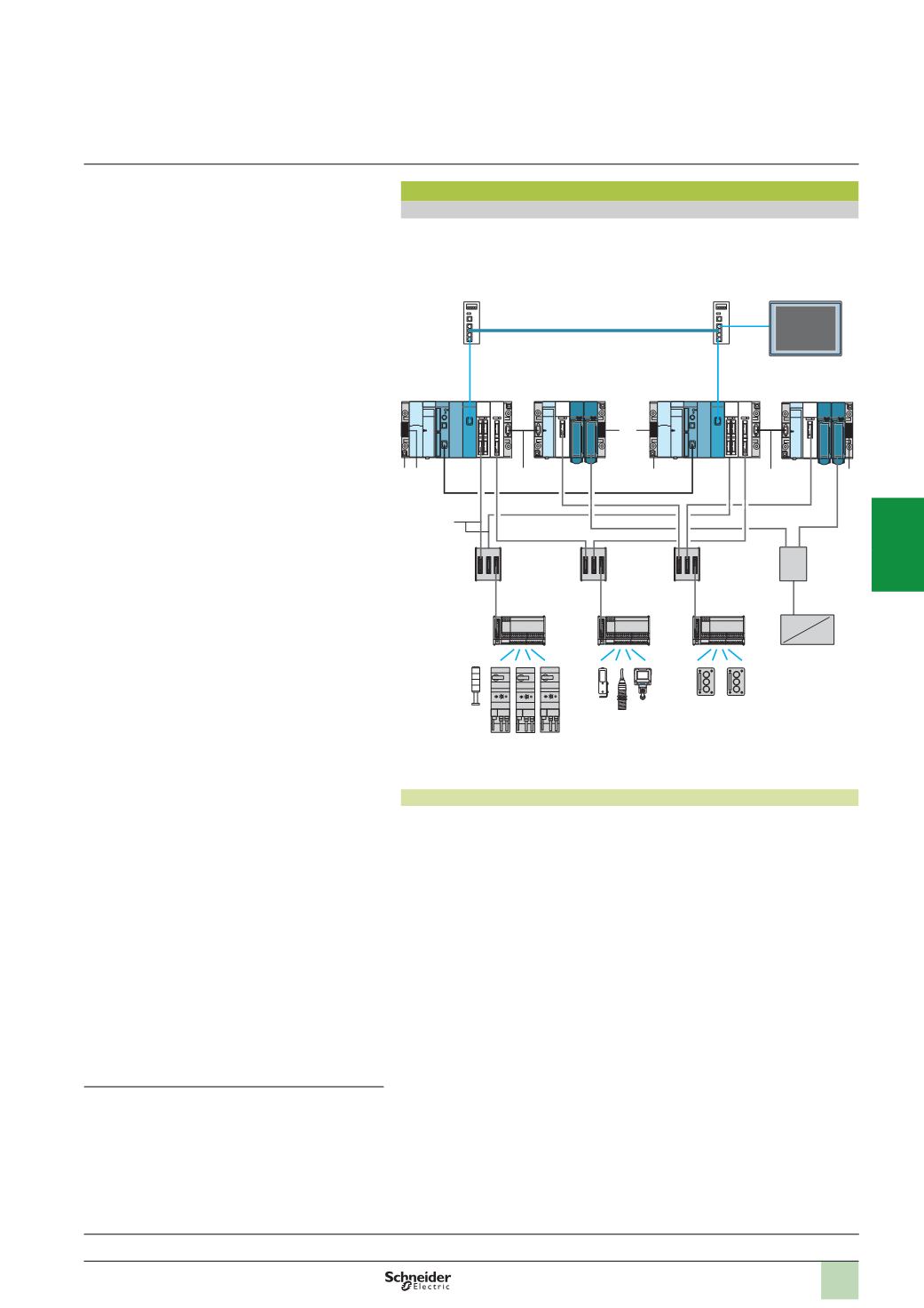
Architecture with redundant I/O on Bus X
In this type of architecture, the discrete and analog I/O on Bus X are redundant
components. The discrete and analog I/O modules controlling them are positioned in
each Primary and Standby single-rack or multi-rack configuration.
Management of redundant I/O
Each Primary and Standby Premium PLC has a set of identical I/O modules on its
TSX RKY
p
rack.
Discrete sensors/actuators are connected to 16-channel Modicon Telefast
ABE
7
H16/S16/R16
passive connection or adaptor sub-bases.
Analog sensors/actuators are connected via the JM Concept converter. Visit the
website
www.jmconcept.comFor the redundant inputs, the sensor data is transmitted to the Primary and Standby
PLCs simultaneously via the 2 identical input modules placed in the Premium racks.
Two 16-channel Modicon Telefast ABE 7 sub-bases,
ABE 7ACC11
with redundant
inputs and
ABE 7ACC10
with redundant outputs, can be used to create double
cabling very easily, using cordsets with two HE10 connectors.
The output values are only generated by the Primary PLC application processing.
This PLC sends its commands to the corresponding output modules. On each scan,
the Standby PLC receives the Primary PLC output values via the CPU Sync link and
applies them to its own outputs. This update ensures a smooth changeover from
Normal to Standby during the changeover time.
Note
:
Output fallback values: in a Hot Standby system, the redundant output modules must be
configured with fallback to state 0, and the shared component outputs (on Ethernet I/O Scanning
or on Modbus) configured with maintain state on fallback.
Note
:
Use of Preventa
TSX PAY 262/282
safety modules: in a Hot Standby system, the modules
are allowed in Premium racks provided that the wiring recommendations are complied with,
please consult your Customer Care Centre.
Architectures
(
continued)
Presentation:
page 4/52
Description:
page 4/53
Functions:
pages 4/58 ...
References:
pages 4/60 ...
Redundant components:
1
Non-expandable rack with 6, 8 or 12 positions
TSX RKY
pp
(
single-rack configuration) or expandable with 4, 6, 8 or 12
positions
TSX RKY
pp
EX
(
multi-rack configuration)
1-
B
Bus X extension cable (multi-rack configuration)
1-
C
Line terminator (multi-rack configuration)
2
Power supply module
TSX PSY
ppp
M
3
Hot Standby processor
TSX H57 24M/44M
4
Ethernet Modbus/TCP network module
TSX ETY 4103/5103
(
version
u
sv 4.0)
5
Analog I/O modules
TSX AEY/ASY
ppp
6
Discrete I/O modules, 16, 28, 32 or 64 channels (1 HE 10
connector for 16 channels)
TSX DEY/DSY/DMY 16/28/32/64
pp
K
Modicon Telefast ABE 7 and JM Concept cabling
components:
21
Redundancy sub-bases:
v
16
as 2 x 16 input channels
ABE 7ACC 11
v
16
as 2 x 16 output channels
ABE 7ACC 10
22
16-
channel passive sub-bases
ABE 7H16
ppp
,
for adaptation
of inputs or outputs (16-channel)
ABE 7S16/7R16/7P16
ppp
23
Cordsets with two HE10 connectors
TSX CDP
pp
3
(0.5, 1, 2,
3, 5
or 10 m long)
24
Analog I/O multiplexer (supplied by JM Concept):
v
Analog inputs
JK 3000 N2
: 1
x 0-20 mA/0-10 V input in
2
x 0-20 mA/0-10 V inputs
v
Analog outputs
GK 3000 D1
: 2
x 4-20 mA outputs in
1
x 4-20 mA output
Ethernet cabling components:
10
ConneXium switch with 4, 8 or 16 10/100BASE-TX ports
499
NES
pp
100
(
unmanaged) or
TCS ESM
pp
3
(
managed)
11
CPU Sync link, copper crossover cable
490
NTC 000
ppp
12
Copper straight-through cable
490
NTW 000
ppp
13
Copper crossover cable
490
NTC 000
ppp
(1)
Human Machine Interface:
19
Magelis XBT GT graphic display terminal with embedded
Ethernet port
XBT GT
pp
30/40
(1)
For Ethernet ring lengths > 100 m, the copper link is
replaced by a fibre optic link, either multimode (3 km max.)
or single-mode (20 km max.) via ConneXium switches
TCS ESM 043F2CS0
and straight-through copper cable
490
NTW 000
ppp
(
fibre optic not supplied by Schneider
Electric).
19
12
10
10
13
23
21
21
21
22
22
22
24
11
3 4 6 6
5 5
2 3 4 6 6
6 5
12
12
1
1
2 5
2
2 6
1-
C
1-
B
1-
B
1-
C
1-
C
Primary
Premium
Standby
Premium
Ethernet Modbus/TCP
XVB
TeSys
Sensors
Control station
Magelis XBT GT
CPU Sync link
Modicon
Telefast ABE 7
Analog sensors
or actuators
Modicon Premium automation
platform
Hot Standby system
Unity Pro software
2
1
3
4
5
6
7
8
9
10