


 301 / 327

TECHNICAL INFORMATION
Technical information
PVC–U domestic and general trunking
| 301
Material
PVC-U is flame retardant and self-
extinguishing. It provides a 100%
recyclable material with good
sustainability.
Installation
Positioning
For surface wiring around ceilings.
Expansion/contraction
PVC-U expands and contracts at a
uniform rate of approx 5.25mm in
a 3 metre length for a temperature
change of 25°C. Therefore, a 3mm gap
between each length of trunking base
is recommended. Fittings allow for
thermal expansion of the covers.
Fitting
• Secure trunking base in one plane
every 500mm by drilling 6mm holes
in the wall side of the trunking and
use round head screws and washers.
• Avoid over-tightening to permit
thermal movement.
• The use of plastic caps over screw
heads is recommended to protect
installed cables.
• To cut the trunking, use a fine-
toothed panel or power jig-saw.
• External profile fittings overlap joints
by up to 10mm to cover cutting
inaccuracies.
• A variable angle jig-saw or chop
saw is recommended for cutting 45°
mitres.
Joints and bends
• Base joints should have a 3mm gap
to allow for expansion.
• Base must be mitred 45˚ to ensure
total closure of trunking.
• End caps with clips ensure security of
trunking.
Covers
Covers are designed to limit
unauthorised removal and to remain
in position during normal conditions
irrespective of impact and minor
undulations of the mounting surface.
Covers – fitting
Covers are clipped into place from
front. For external moulded fittings, a
gap of 25mm is left between the two
cover ends to permit the fitting to clip
to base.
Covers – removal
To remove a cover, first remove a fitting
to gain access. Insert blade of terminal
screwdriver between captive legs of
cover and base and gently ease off.
Accessories
Accessories are serviced through a
spur using a mini trunking adaptor and
mini trunking across the ceiling to a
pendant drop or down the wall to an
appropriate accessory box.
Cable capacity chart
Cable
factor Compartment 1
PVC power cable
1.5mm
2
stranded copper
8.0
47
PVC power cable
2.5mm
2
stranded copper
11.9
31
PVC power cable
4.0mm
2
stranded copper
16.6
22
Data cable: Ø5.5mm
23.8
15
Data cable: Ø6.0mm
28.3
13
Data cable: Ø6.5mm
33.2
11
Data cable: Ø7.0mm
38.5
9
Data cable: Ø8.4mm
55.4
6
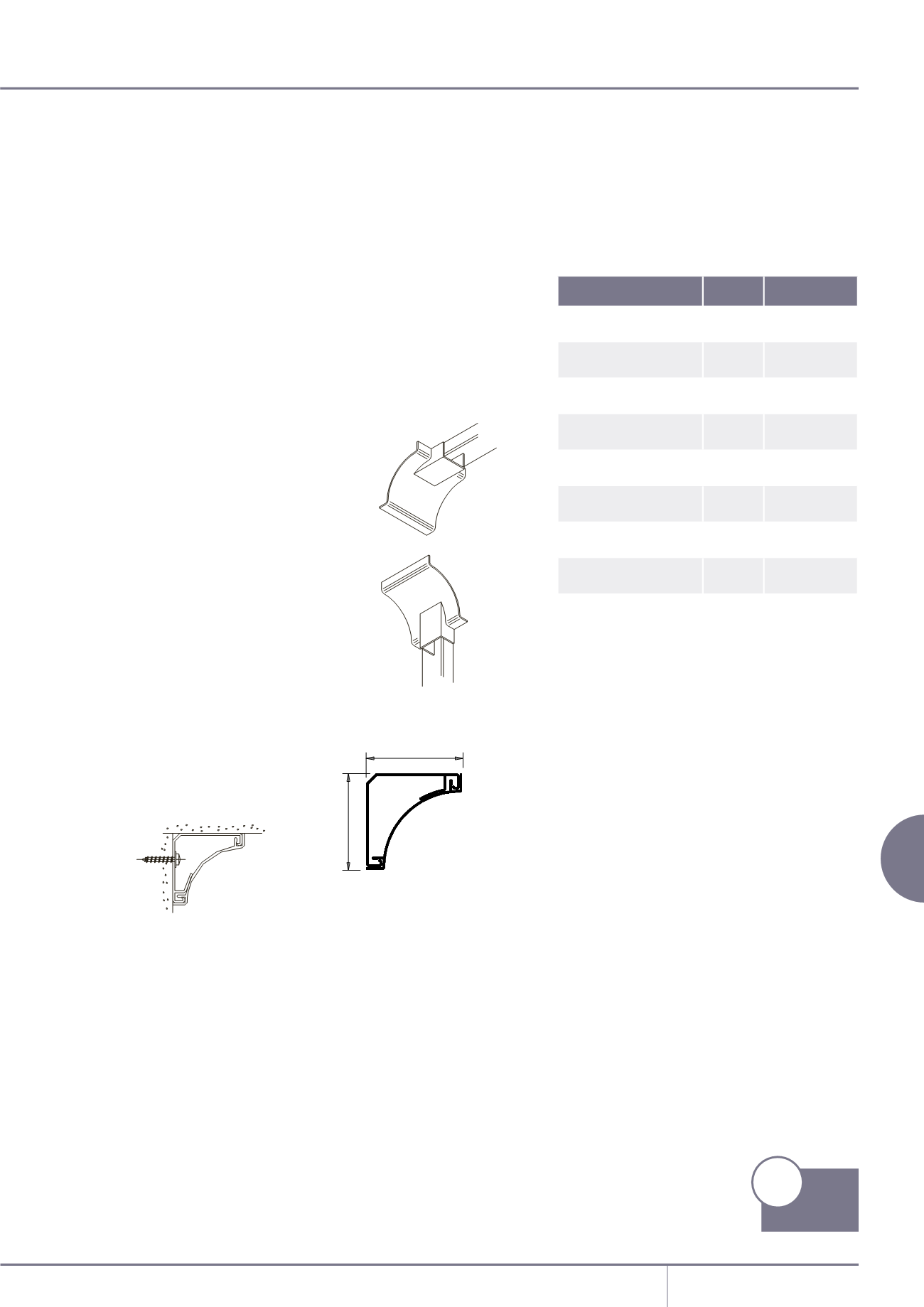
CEILING
APPLICATION
VERTICAL WALL
APPLICATION
CEILING
WALL
Cable capacities
• All calculations allow for a
45% space factor.
As there can be differences between
data cable sizes, Marshall-Tufflex
recommend that cable dimensions
are confirmed with the manufacturing
company.
Cornice trunking
Dimensions
CEILING
APPLICATION
VERTICAL WALL
APPLICATION
CEILING
WALL
p211
Product
Information
1 = 837mm
2
total area
1 = 376mm
2
45% space factor
1
50
50