


 306 / 327

Tel
+44 (0)1424 856600
Fax
+44 (0)1424 856611
Technical Hotline
+44 (0)1424 856688
TECHNICAL INFORMATION
Technical information
306 |
PVC–U domestic and general trunking
Material
PVC-U is flame retardant and self-
extinguishing. It provides a 100%
recyclable material with good
sustainability.
Installation
Positioning
Suitable for skirting and architrave
installation. When used as a skirting
system, sufficient clearance should be
allowed between the floor covering
and the profile fittings that clip over
the cover i.e. 5mm + floor covering is
recommended.
Expansion/contraction
PVC-U expands and contracts at a
uniform rate of approx 5.25mm in
a 3 metre length for a temperature
change of 25°C. Therefore, a 3mm gap
between each length of trunking base
is recommended. Fittings allow for
thermal expansion of the covers.
Fitting
• Secure base every 500mm by drilling
alternate 6mm in the two outer slots
provided.
• Secure using No 8 round head screws
and washers.
• Avoid over-tightening to permit
thermal movement. Internal couplers
on base units not required.
• To cut the trunking, use a fine-
toothed panel or power jig-saw.
• External profile fittings overlap joints
by up to 10mm to cover cutting
inaccuracies.
• A variable angle jig-saw or chop
saw is recommended for cutting 45°
mitres.
• For segregation, use the cable
retainers to retain cables in correct
compartments.
Single lengths
Where it is required to fit a single
length of trunking (under 3 metres)
between two inside walls and no
accessory box is fitted, it is advisable to
install a coupler in the centre of the run
to facilitate the removal of the cover.
Joints and bends
• Base joints should have a 3mm gap
to allow for expansion.
• Mitre bases for internal bends,
external bends and flat angles at 45°
to ensure total enclosure of trunking.
• External moulded fittings overlap
the joints by up to 10mm to cover
cutting inaccuracies.
• Trunking cover holds external
moulded fittings in place when they
are clipped on to base.
Bend radius control
Not available.
Accessory boxes
• Mounted on to trunking body with
accessory external to the trunking.
• Remove required knockout in back
segregator plate that aligns with
trunking cable compartment.
• Clip to trunking base and secure
to wall surface using 2 diagonally
opposite fixing holes.
• Feed cables through knockout.
• After trunking cover has been fitted
to base, clip front cover plate to back
plate.
• Complete assembly is finally secured
together when the wired accessory is
screwed to accessory front plate.
Covers
Covers are designed to limit
unauthorised removal and to remain
in position during normal conditions
irrespective of impact and minor
undulations of the mounting surface.
Covers – fitting
Covers are clipped into place from
front. If accessory boxes are installed,
covers are butt-joined to the edge of
the box assembly. Cut edges of the
cover are concealed by the accessory.
For fittings, a gap of 4mm is left
between the two cover ends to permit
the fitting to clip to base.
Covers – removal
To remove a cover, isolate circuit
and detach an accessory and front
mounting component. Insert blade of
screwdriver between captive legs of
cover and gently peel off.
Screening
Not available.
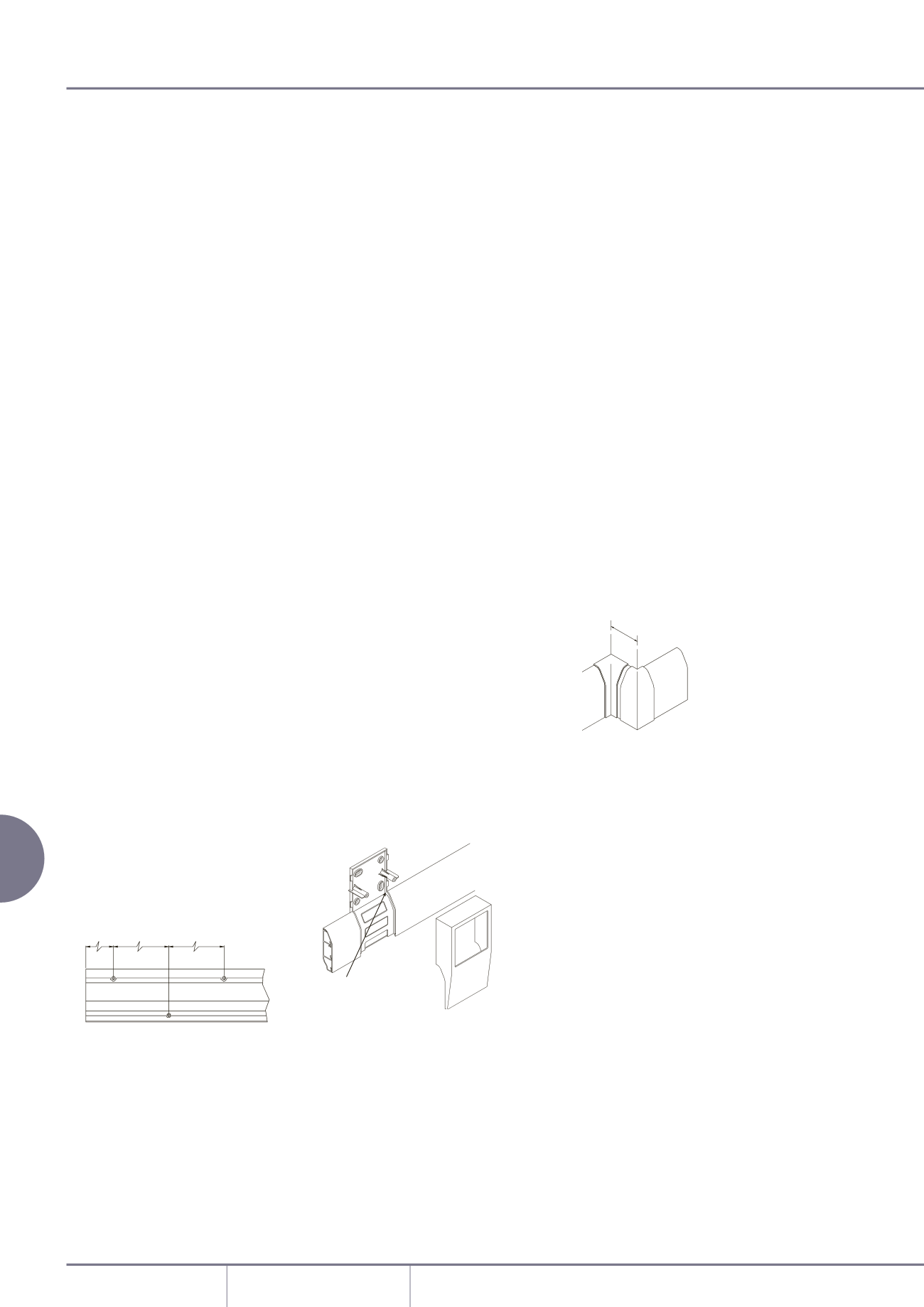
Offset dimensions
The minimum set that can be
accommodated in the same plane
(from internal to external bend), is
shown below:
500mm 500mm
50mm
Sovereign Plus trunking
42 min
Adaptor
Back Plate
Accessory
Cover
Plate
segregator
Insert small
screwdriver
Lift on top edge
to break seal
42 min
Adaptor
Back Plate
Accessory
Cover
Plate
Segregator
Insert small
screwdriver
Lift on top edge
to break seal