


 305 / 327

TECHNICAL INFORMATION
Technical information
PVC–U domestic and general trunking
| 305
Material
PVC-U is flame retardant and self-
extinguishing. It provides a 100%
recyclable material with good
sustainability.
Installation
Positioning
As feeder trunking.
Expansion/contraction
PVC-U expands and contracts at a
uniform rate of approx 5.25mm in
a 3 metre length for a temperature
change of 25°C. Therefore, a 3mm gap
between each length of trunking base
is recommended. Fittings allow for
thermal expansion of the covers.
Fitting
•
Mini trunking
• Secure trunking base at lease every
375mm by drilling 6mm holes.
• Fasten using roundhead screws.
•
Self-fixing mini trunking
• Remove protective film exposing
100-150mm of adhesive foam.
• Line up accurately and press firmly
into position.
• Repeat until base is installed.
• For long term performance we
recommend additional securing with
screws and washers.
Note:
the bond created by the tape can
be very strong. Maximum adhesion
occurs after 24 hours. Ensure surface is
dust-free, dry, clean and flat. Uneven
surface contact will reduce bonding
performance. Installation in cold
conditions below +5˚c may affect
adhesion.
Mini and Mini SF trunking
• Avoid over-tightening to permit
thermal movement.
• The use of plastic caps over screw
heads is recommended to protect
installed cables.
• To cut the trunking, use a fine-
toothed panel or power jig-saw.
• External profile fittings overlap joints
by up to 10mm to cover cutting
inaccuracies.
• A variable angle jig-saw or chop
saw is recommended for cutting 45°
mitres.
• End caps are secured using adhesive
solvent MSC.
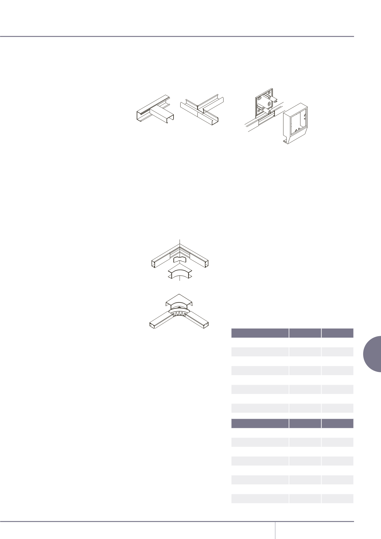
Joints and bends
• All fittings incorporate clip-on design.
• 3mm gap between trunking base
and bend or flat angle is
recommended.
• For internal bends and flat angles,
bases should be mitred 45˚.
• For external bends, bases should be
cut square to the corner.
• For tees, bases should be cut square
and butt up to each other.
• External clip on fittings overlap
trunking base by up to 10mm to
cover cutting inaccuracies.
• Secure end caps using solvent
adhesive MSC3.
Bend radius control – MMT4 only
• For internal bends, base should be
mitred at 45°
• For external bends, base should be
cut square with the corner and the
radius control fitted.
• For flat angles and tees, allowance
should be made when cutting base,
for moulded components.
Accessory boxes
• Select appropriate surface box.
• Remove required knockout.
• Clean burrs from around aperture.
• Snap mini adaptor into position on
box and place in position.
• Ensure trunking seats securely into
adaptor.
• Secure box using diagonally opposite
fixing holes.
Shrouded entry boxes
• For use with MMT2 or MMT3 only.
• Fit back plate in position, secure
using diagonally opposite fixing
holes.
• Run mini base up to back plate (for
terminal accessory) or continue
through.
• Remove required knockout from
outer cover to fit mini trunking and fit
over base plate. Install wiring leaving
sufficient to wire accessory.
Conductor type
Size
Cable factor
Stranded PVC power
1.5mm
2
8.0
Stranded PVC power
2.5mm
2
11.9
Stranded PVC power
4.0mm
2
16.6
*Data cable
Ø5.5mm 23.8
*Data cable
Ø6.0mm 28.3
*Data cable
Ø6.5mm 33.2
*Data cable
Ø7.0mm 38.5
*Data cable
Ø8.4mm 55.4
Mini trunking
Size mm 45%capacity
MMT100
10 x 8
18.5mm
2
MMT0
16 x 10
42mm
2
MMT1
16 x 16
77.2mm
2
MMT2
25 x 16
119.7mm
2
MMT3
38 x 16
193mm
2
MMT4
38 x 25
342mm
2
MMT5
50 x 25
449mm
2
MMT6
38 x 38
501mm
2
MMT7
75 x 16
397mm
2
50mm radius internal
50mm radius
Cable capacities
• All calculations allow for a
45% space factor.
• Divide cable factor (1st table) into
capacity (2nd table) to ascertain
number of cables.
As there can be differences between data
cable sizes, Marshall-Tufflex recommend
that cable dimensions are confirmedwith
themanufacturing company.
Mini trunking
• Complete assembly is finally secured
together when the wired accessory is
screwed to accessory front plate.
• Fit mini trunking cover to base,
ensuring cover extends into
knockout.
Covers
Covers are designed to limit
unauthorised removal and to remain
in position during normal conditions
irrespective of impact and minor
undulations of the mounting surface.
Covers – fitting
Covers are clipped into place from
front.
Covers – removal
To remove a cover, first detach a
coupler or internal/external bend to
gain access. The cover can then be
gently eased off the base.