


 300 / 327

Tel
+44 (0)1424 856600
Fax
+44 (0)1424 856611
Technical Hotline
+44 (0)1424 856688
TECHNICAL INFORMATION
Technical information
300 |
PVC–U domestic and general trunking
Material
PVC-U is flame retardant and self-
extinguishing. It provides a 100%
recyclable material with good
sustainability.
Installation
Positioning
If used as a skirting system, a clearance
of 5mm is recommended above the
floor covering to allow the profile
fittings to clip over the cover.
Bench and desk installations: a single
run can be fitted to rear of furniture
or, if run down centre line, two units
can be joined back to back presenting
accessories on both sides.
Expansion/contraction
PVC-U expands and contracts at a
uniform rate of approx 5.25mm in
a 3 metre length for a temperature
change of 25°C. Therefore, a 3mm gap
between each length of trunking base
is recommended. Fittings allow for
thermal expansion of the covers.
Fitting
• Secure trunking base in one plane
only every 500mm by drilling
alternative 6mm holes either side of
divider nib.
• Avoid over-tightening to permit
thermal movement.
• The use of plastic caps over screw
heads is recommended to protect
installed cables.
• To provide cable segregation,
dividing fillets are snapped on to
internal nibs in base.
• To cut the trunking, use a fine-
toothed panel or power jig-saw.
• External profile fittings overlap joints
by up to 10mm to cover cutting
inaccuracies.
• Accepts Marshall-Tufflex and
standard UK wiring and data
accessories.
Single lengths
Where it is required to fit a single
length of trunking (under 3 metres)
between two inside walls and no
accessory box is fitted, it is advisable to
install a coupler in the centre of the run
to facilitate the removal of the cover.
Joints and bends
• Base joints should have a 3mm gap
to allow for expansion.
• Internal and external bends are
prefabricated.
• External moulded fittings overlap the
joints to cover cutting inaccuracies.
• Couplers are required to align and
join bend assemblies to trunking.
• Secure end caps using solvent
adhesive MSC3.
Accessory boxes
• Remove the appropriate knock
out that aligns with segregated
compartment containing supply
cable and clip the box into the
trunking base.
• When boxes are installed
consecutively, a 14mm wide spacer
(ES1) is required to cover the space
between the boxes.
• Part M box assemblies with
contrasting coloured faceplates are
available to meet the requirements
of DDA regulations for Visual
Impairment.
Covers
Covers are designed to limit
unauthorised removal and to remain
in position during normal conditions
irrespective of impact and minor
undulations of the mounting surface.
Covers – fitting
Covers are clipped into place from
front. If accessory boxes are installed,
the cover is butt-joined to the edge
of the box . Cut edges of the cover are
concealed by the accessory.
For couplers, a gap of 25mm is left
between the two cover ends to permit
the fitting to clip to base.
Covers – removal
To remove a cover, first detach a
coupler to gain access. The cover can
then be gently eased off the base.
Antimicrobial
For technical details of antimicrobial
Bio Bench trunking, please refer to
Laboratory and Healthcare section.
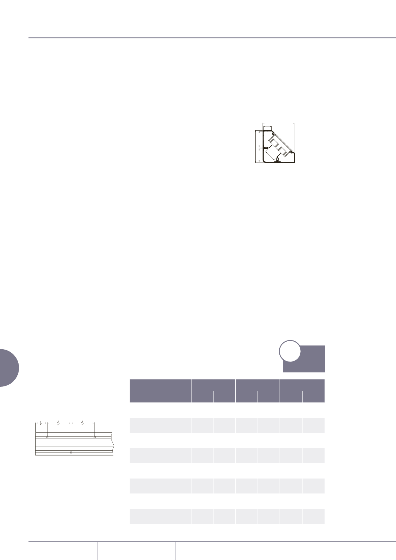
Dimensions
Bench trunking – with box
1 = 1285mm
2
total area
1 = 578mm
2
45% space factor
2 = 2128mm
2
total area
2 = 957mm
2
45% space factor
3 = 1285mm
2
total area
3 = 578mm
2
45% space factor
Bench trunking – no box
1 = 1782mm
2
total area
1 = 802mm
2
45% space factor
2 = 3282mm
2
total area
2 = 1477mm
2
45% space factor
3 = 1782mm
2
total area
3 = 802mm
2
45% space factor
500mm 500mm
50mm
A
A
B
26
42
38
51
105
105
1
3
2
Bench trunking
Cable capacities
• All calculations allow for a 45% space
factor.
As there can be differences between
data cable sizes, Marshall-Tufflex
recommend that cable dimensions
are confirmedwith themanufacturing
company.
Cable capacity chart
Compartment 1 Compartment 2 Compartment 3
No box With box No box With box No box With box
PVC power cable
1.5mm
²
stranded copper
100
72
185
120
100
72
PVC power cable
2.5mm
²
stranded copper
67
49
124
80
67
49
PVC power cable
4.0mm
²
stranded copper
48
35
89
58
48
35
Data cable: Ø5.5mm
34
24
62
40
34
24
Data cable: Ø6.0mm
28
20
52
34
28
20
*Data cable: Ø6.5mm 25
18
46
30
25
18
*Data cable: Ø7.0mm 21
15
38
25
21
15
*Data cable: Ø8.4mm 14
10
27
17
14
10
*Only for straight runs. If bends are required please contact the Technical Team on +44 (0)1424 856688.
p209
Product
Information