


 298 / 327

Tel
+44 (0)1424 856600
Fax
+44 (0)1424 856611
Technical Hotline
+44 (0)1424 856688
TECHNICAL INFORMATION
Technical information
298 |
Steel trunking systems
Steel trunking Series 130 and Series 170
Single lengths
Where it is required to fit a single length
of trunking (under 3 metres) between two
inside walls and no accessory box is fitted,
it is advisable to install a coupler in the
centre of the run to facilitate the removal of
the cover.
Joints and bends
• Base joints should be aligned and butt
jointed together.
• Internal and external bends, flat angles
and tees are prefabricated in steel,
aligned and butt jointed to the base using
coupling bonding sets.
• Clip-on external tolerance sleeve overlaps
the joints to cover minor inaccuracies.
Screening
Steel containment protects internal circuits
from external electromagnetic interference.
For internal segregation and screening, use
the steel dividing fillet 351189.
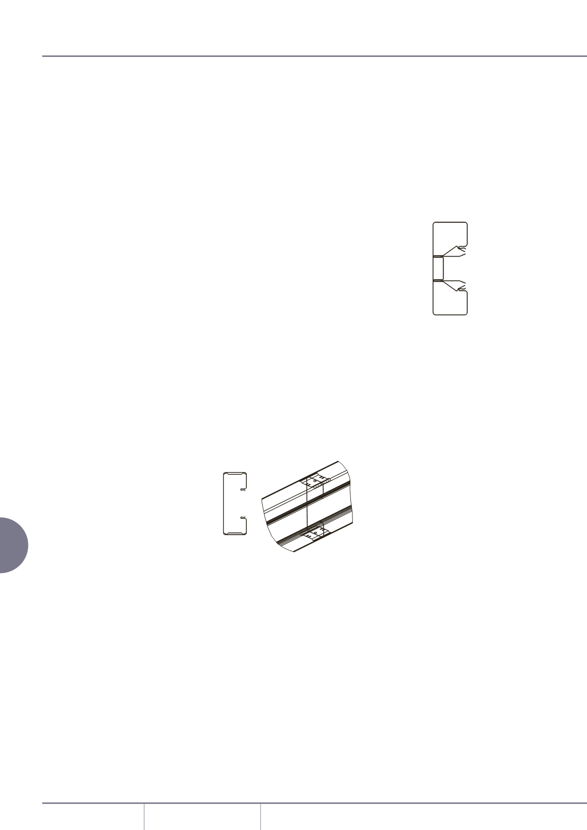
Internal coupling/bonding set
• Comprises of two identical parts.
• Insert both parts into end of one length of
trunking. Slide next section of base onto
couplers and fix into position.
Accessory boxes
Standard depth 40mm
Remove the appropriate box knockout
and clip each side of the box into the
trunking base.
When boxes are installed consecutively, use
cover spacer WG01085 between adjacent
boxes.
Dividing fillet
Dividing fillet 351189 is supplied in 1
metre lengths. It is held in place through
using the universal multi-purpose clip. A
minimum of 3 clips are required to hold 2
lengths of the dividing fillet in place.
The trunking can be divided into up to 3
compartments using the dividing fillet.
Please refer to element 3 of the diagram on
page 187.
Covers
Covers are designed to limit unauthorised
removal and to remain in position during
normal conditions irrespective of impact
and minor undulations of the mounting
surface.
Covers – fitting
Covers are clipped into place from front.
If accessory boxes are installed, covers
are butt-joined to the edge of the box
(RSSB10WH end RSSB20WH). Cover lengths
are determined so that ends are covered by
a fitting or accessory. External bends and
flat angles should be fitted with the correct
bend/flat
angle cover.
Covers – removal
To remove a cover, first detach an external
joint cover or accessory to gain access. The
main cover can then be gently eased off
the base.
Material
Steel trunking is manufactured from pre-
galvanised steel with a powder coat finish
to RAL 9010.
Installation
Positioning
• System 130: suitable for dado installation.
• System 170: suitable for dado and skirting
installation.
When used as a skirting system, sufficient
clearance should be allowed between
the floor covering and the profile fittings
that clip over the cover i.e. 5mm + floor
covering is recommended.
Fitting
• Secure trunking base every 750mm.
• Secure using No 8 round head screws and
washers using the grooves in the outer
compartments of the base to facilitate
drilling 6mm holes.
• Avoid over-tightening to permit thermal
movement.
• The use of plastic caps over screw heads is
recommended to protect installed cables.
• To cut the trunking, use a fine tooth blade
(32/36tpi) or, preferably,a circular saw with
a 350mm fine tungsten blade (90/108tpi).
This will produce an edge requiring
minimal de-burring.
• Consecutive lengths of base are aligned
and butt jointed together using the
coupling/bonding set.
Earthing
• Trunking base, main fittings and
accessories are fitted with earth
connections.
• Bonding base to fittings: use coupling/
bonding set or wire between fitted earth
connections.
• Bonding base to cover: covers have
pressed out side grippers which
automatically establish earth contact
when pressed into trunking base.
• Bonding base to end caps: use bonding
strap LBS3.