


 296 / 327

Tel
+44 (0)1424 856600
Fax
+44 (0)1424 856611
Technical Hotline
+44 (0)1424 856688
TECHNICAL INFORMATION
Technical information
296 |
Aluminium trunking systems
Material
Aluminium trunking is manufactured
from high precision extruded
aluminium with a powder coat finish.
Accessory boxes are supplied in PVC-U
or polycarbonate both of which are
100% recyclable.
Installation
Positioning
For dado and skirting installation. When
used as a skirting system, sufficient
clearance should be allowed between
the floor covering and the profile
fittings that clip over the cover i.e. 5mm
+ floor covering is recommended.
Fitting
• Secure trunking base every 750mm.
• Secure using No 8 round head screws
and washers using the grooves in the
outer compartments of the base to
facilitate drilling 6mm holes.
• Avoid over-tightening to permit
thermal movement.
• The use of plastic caps over screw
heads is recommended to protect
installed cables.
• To cut the trunking, use a fine tooth
blade (32/36tpi) or, preferably,a
circular saw with a 350mm diameter
fine tungsten blade (90/108tpi).
This will produce an edge requiring
minimal de-burring.
• Consecutive lengths of base are
aligned and butt jointed together.
Earthing
• Clean protective coating from base,
covers and metallic fittings and then
earth bond.
• Incoming earth connection is made
using LTB1 bonding assembly
installed in the earth channel of the
base.
• Bonding base to base: in final ring or
radial 32Amp circuits, bonding strap
LBS1 can be used.
• Bonding covers and end caps to base:
use bonding strap LBS2.
Single lengths
Where it is required to fit a single
length of trunking (under 3 metres)
between two inside walls and no
accessory box is fitted, it is advisable to
install a coupler in the centre of the run
to facilitate the removal of the cover.
Joints and bends
• Moulded from colour-matching
polycarbonate.
• External bends: base should be cut
square at the corner and the internal
segregator inserted into the web of
each base.
• Internal bends: base must be mitred
45° to ensure total enclosure of
trunking, including any internal fitted
segregator.
• Flat angles, tees and crossovers are
prefabricated aluminium.
• External moulded fittings overlap the
joints by up to 10mm to cover cutting
inaccuracies.
Bend radius control
For data bend radius control fittings for
XL, please contact the Technical Team
on +44 (0)1424 856688.
Accessory boxes
• If accessory box in main compartment
is supplied from an outer
compartment, drill the main web
adjacent to the box position.
• Remove the appropriate knock out
and clip the box into the trunking
base.
• For boxes in the same compartment
as the supply, remove the appropriate
box knock-outs and clip the box into
trunking base.
• When boxes are installed
consecutively, a 14mm minimum
space is required to cover the space
between the boxes (use PVC-U
ES1WH or use section of aluminium
cover)
• Part M box assemblies with
contrasting coloured faceplates are
available to meet the requirements
of DDA regulations for Visual
Impairment.
Covers
The covers have been designed to
remain in position irrespective of
impact during normal conditions,
minor undulations of the mounting
surface, and to limit unauthorised
removal.
Covers – fitting
Covers are clipped into place from the
front. If accessory boxes are installed,
the LTL1 covers are butt-joined to the
edge of the box (ESSB1 and 2 only) and
the cut edges of lids are subsequently
concealed by the accessory. For fittings,
a gap of 30mm is left between the two
cover ends to permit the fitting to clip
to the base.
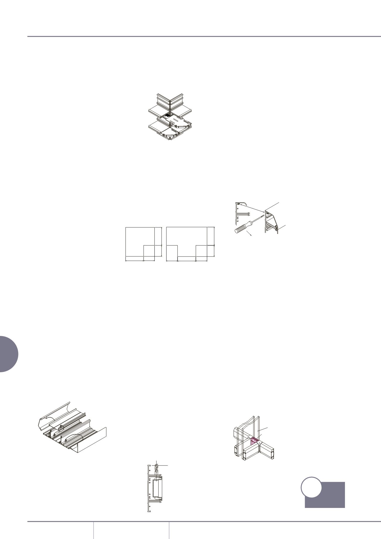
Covers – removal
To remove a cover, first detach a
coupler, internal or external bend
component to gain access. The main
cover can then be gently eased off
the base. To remove the outer cover,
firstly ease from the base by inserting
the blade of a terminal screwdriver
between the captive legs of the cover
and the base and then peel off.
Screening
Aluminium containment will protect
all internal circuits from external
electromagnetic interference. For
internal segregation and screening, use
a screened dividing fillet.
Method of continuation through
a partition wall
Continue the main lateral run of base
through the partition wall with short
lengths of cover fitted where the
trunking passes through the partition.
The partition wall trunking is then
butted up to the main run and the
joint covered by an Internal bend. (as
shown below)
DRILL HOLE OF
SUITABLE SIZE
INSERT SCREWDRIVER
INTO SHADED AREA
LEVER OUT
PARTITION WALL
COVERS TO BE FITTED
BEFORE BASE IS INSTALLED
XL trunking aluminium
X
100mm
X
100mm
100mm
X
100mm
X
100mm
X
100mm
X
100mm
100mm
X
100mm
X
100mm
220mm
308mm
220mm
308mm
Template dimensions for
Flat angle and Tee
p170
Product
Information