


 292 / 327

Tel
+44 (0)1424 856600
Fax
+44 (0)1424 856611
Technical Hotline
+44 (0)1424 856688
TECHNICAL INFORMATION
Technical information
292 |
Aluminium trunking systems
Covers
Covers are designed to limit
unauthorised removal and to remain
in position during normal conditions
irrespective of impact and minor
undulations of the mounting surface.
Covers – fitting
Covers are clipped into place from
front. If accessory boxes are installed,
the LTL1 cover is butt-joined to the
edge of the box. Cut edges of the cover
are subsequently concealed by the
accessory. For fittings, a gap of 25mm
is left between the two cover ends to
permit the fitting to clip to base.
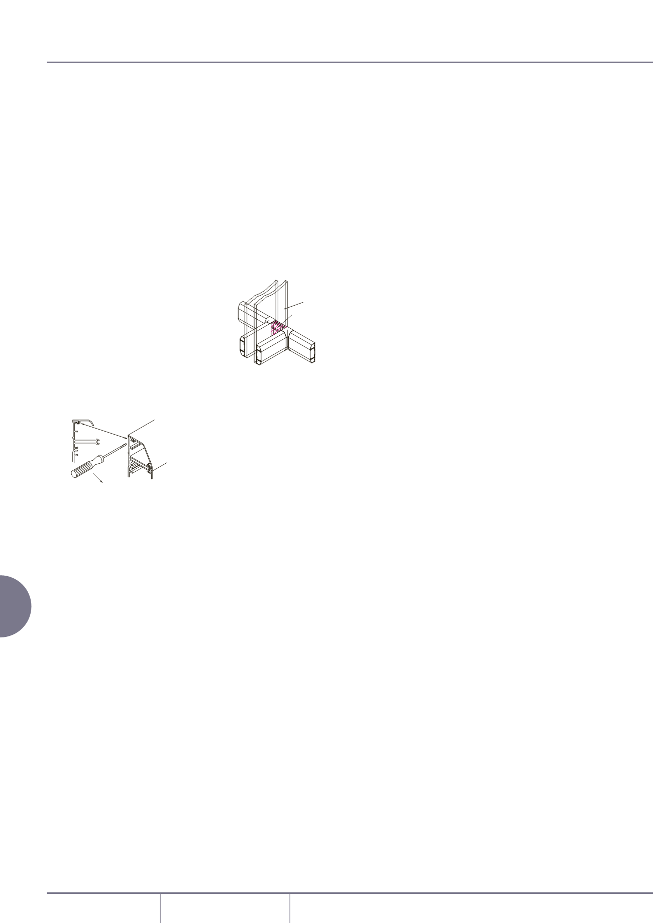
Covers – removal
To remove a cover, first detach a
coupler, internal or external bend
component to gain access. The main
cover can then be gently eased off
the base. To remove the outer cover,
firstly ease from the base by inserting
the blade of a terminal screwdriver
between the captive legs of the cover
and the base and then ease away from
the base.
INSERT SCREWDRIVER
INTO SHADED AREA
LEVER OUT
PARTITION WALL
COVERS TO BE FITTED
BEFORE BASE IS INSTALLED
Screening
Aluminium containment will protect
all internal circuits from external
electromagnetic interference. For
internal segregation and screening, use
a screened dividing fillet.
Method of continuation through
a partition wall
Continue the main lateral run of base
through the partition wall. Fit short
lengths of cover where the trunking
passes through the partition. The
partition wall trunking is then butted
up to the main run and the joint
covered by an internal bend fitting.