


 475 / 759

475
WIRING DEVICES
Technical Hotline
+44 (0)1268 563720
6.5
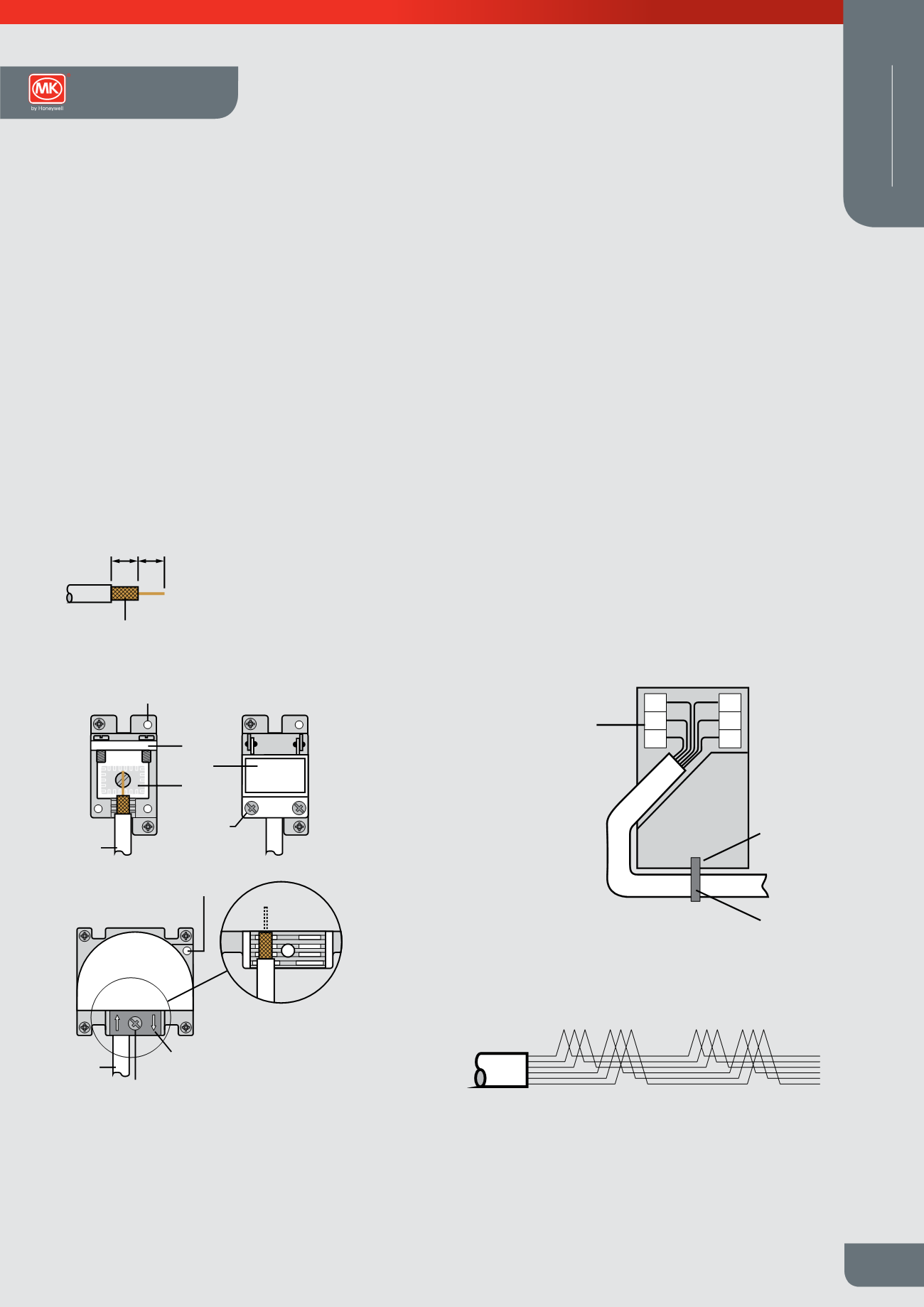
Screening braid to remain in
place over the inner insulation
6.5
TV Co-axial cable stripping details
Earth terminal
Co-axial
cable
Foil EMC
screening
gasket
Clamping
plate fixing
screws
Cable
clamping
plate
Earth
terminal
Clamping
fixing screws
View with cable
clamp removed
Cable clamp
Co-axial
cable
Installation
l
When installing the TV co-axial cable ensure
that all cable bends are smooth so that the
inner insulation is not crushed or squashed,
otherwise the TV signal quality may be
affected
l
Not suitable for loop-in loop-out installations
l
Use CT100 cable (or equivalent)
Digital TV/FM and Telephone Outlets
(Logic Plus and Modular Datacoms)
Telephone Outlet Connection
Carefully strip 50mm of the telephone cable outer sheath to expose the inner
insulated conductors. Using the insertion tool supplied, (MK List no. 400NAT)
carefully push each lead into the appropriate IDC terminals according to the wiring
colour code stated in the telephone Wiring Scheme diagram.
Pins 1 and 6 are frequently unused, 4 wire cable may be used in these installations.
If an existing installation uses a different wiring colour code system, this should be
retained on any new or extended installation.
Additional secondary extension outlets should be wired in parallel with the existing
installation via the IDC terminals, (i.e. pin 1 to pin1, pin 2 to pin 2, etc).
In the event that the earth terminal is required to be used, the installer must ensure
that a suitable earth conductor is present to connect to the earth terminal. (In the
case of 2G products both TV modules should be earthed).
In the event that the earth terminal is required to be used, the installer must ensure
that a suitable earth conductor is present to connect to the earth terminal. (In the
case of 2G products both TV modules should be earthed).
1 2 3 4 5 6
1 2 3 4 5 6
First Socket Outlet
Master
Extension Outlet
Secondary
IDC
terminals
2
3
4
6
5
Cable tie
Cable Tie
fixing point
1
Telephone Wiring
Scheme
1 GREEN / white
2 BLUE / white
3 ORANGE / white
4 WHITE / orange
5 WHITE / blue
6 WHITE / green
Note: Main wire colour is shown in capitals
Wiring Devices Technical