


 435 / 582

BETA Measuring
Three-Phase Measuring Devices
7
KT1 5 E-counters
11/19
Siemens ET B1 · 10/2008
11
■
Overview
E-counters are used to measure the power consumption in 3-phase
systems, e.g. in industrial plants, offices and apartments in
apartment houses.
Cost pressures are growing, particularly in industry. Product
operating times are reduced and manufacturing facilities must
be retrofitted more frequently. The load levels of the distribution
boards during operation are therefore constantly under observation
in order to avoid peak loads in a timely manner or to perform
retrofitting.
The versions can be used for consumption analysis and minimization
of operating costs in industrial plants and office buildings. The
device versions with LAN interfaces allow a readout to be
performed easily using an existing LAN network.
The devices indicate 6 measured values on an LCD display:
Active energy rate 1 and rate 2, reactive energy rate 1 and
rate 2, active power and reactive power. This means that the
current load of a distribution board can be read out.
■
Benefits
•
The measurement data are constantly stored as a text file with
a time and date stamp. This allows users to create flexible
designs for their own specific solutions (e.g.with MS Excel)
•
The devices indicate the instantaneous power in addition to
the consumption, providing an overview of plant capacity
utilization at all times and saving additional measuring devices
into the bargain
•
For practically unlimited use: E-counters for direct connection,
63
A for small plants and up to 5000 A with transformer for
large plants.
■
Function
E-counters with LAN coupler on LAN
The 7KT1 390 LAN couplers support connection of up to
10 7
KT1 52 E-counters to a LAN network.
For more information on LAN operation and the MS Excel operator
interface, see 7KT1 390 LAN couplers
see page 11/16 ff
.
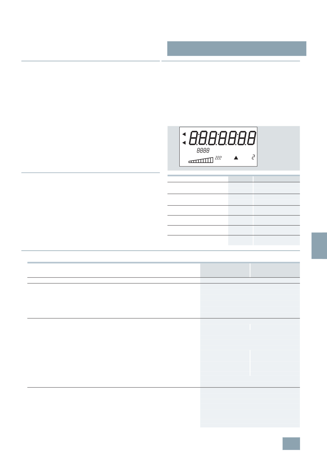
Display
The display of the E-counters comprises a 7-digit 7-segment display
for measured quantities and additional function indications:
■
Technical specifications
Unit
ID
Active energy
Rate 1 kWh
Arrow and T1
Rate 2 kWh
Arrow and T2
Reactive energy
Rate 1 kvarh
Arrow and T1
Rate 2 kvarh
Arrow and T2
Active power
kW
Utilization and
instantaneous value
Reactive power
kvar
Utilization and
instantaneous value
Phase-sequence
indication
1 – 2 – 3
Flashing triangle next to
left-hand phase sequence
Transformer primary
current
5 ... 5000
A CT (current transformer)
I2_10805a
k M
T1 T2
Wvar
kvarh
kWh
1
2 3
0
CT
T
7
KT1 500, 7KT1 502,
7
KT1 510, 7KT1 512,
7
KT1 520
7
KT1 501, 7KT1 503,
7
KT1 511, 7KT1 513,
7
KT1 521
Standards
EN 61010-1, EN 62053-11, -21, -31
Supply
•
Rated control supply voltage U
c
V AC
230
•
Operating range
× U
c
0.80 ... 1.20
•
Rated frequency
Hz
50
•
Frequency ranges
Hz
45 ... 65
•
Rated power dissipation P
v
VA
10
Measuring inputs
•
Connection type
Direct
Transformer /5 A
•
Voltage U
e
Phase/phase
V
400
Phase/N
V
230
•
Operating range voltage
Phase/phase
V
87 ... 480
Phase/N
V
50 ... 276
•
Current
I
e
A
63
5
•
Operating range current
Direct connection
A
0.3 ... 63
--
Transformer connection
A
--
0.012 ... 5
•
Transformer current
Primary current
A
--
5 ... 5000
Smallest input step
A
--
5
•
Frequency
Hz
50
•
Frequency ranges
Hz
45 ... 65
Overload capability
•
Voltage U
e
Continuous: phase/phase
V
480
1
second: phase/phase
V
800
Continuous: phase/N
V
276
1
second: phase/N
V
460
•
Current
I
e
Continuous
A
76
0.5
second
A
--
10
ms
A
2000
© Siemens AG 2008