


 434 / 582

BETA Measuring
Three-Phase Measuring Devices
7
KT1 39 LAN couplers
11/18
Siemens ET B1 · 10/2008
11
■
More information
Connection of the LAN coupler to a LAN
Each station in a LAN must be assigned its own IP address. On
delivery, or after a reset, the LAN coupler has a standard IP address.
The new IP address must be set in the LAN coupler during
commissioning. To do this, the LAN coupler must be directly
connected to a PC using a so-called "cross-over" cable. This is
a network cable in which the transmit and receive wires are
cross-connected. This creates a small LAN with 2 stations, PC
and LAN coupler can communicate with each other directly. The
supplied LAN coupler configuration tool must be installed on
the PC. This direct connection can then be used to set a new
IP address in the LAN coupler, as well as other network parameters,
such as subnet mask and default gateway. The LAN coupler
must then be connected to the target system as communication
is subsequently only possible with the new settings.
Connection of measuring devices to the LAN coupler
E-counters and multicounters are connected to the
LAN couplers over their communication interface. The network
is an RS 485 network in which devices are connected over a
shielded 2-wire cable. When using Modbus, the device address
and transmission rate must be set in the multicounters. This is
not necessary if using the multicounters and E-counters over the
LAN coupler, as the LAN coupler automatically detects and
identifies any connected E-counters and multicounters. You can
now use the LAN coupler configuration tool (over the LAN network)
to tell the LAN coupler the device from which you want to retrieve
the measurement data.
The LAN coupler carries out a so-called "polling" during runtime.
This cyclically retrieves the most recently gathered measurement
data from the measuring devices and buffers them in the
LAN coupler. This can then be called up at any time over the
LAN.
Data transmission from LAN coupler to PC
This data transmission is PC-controlled. A software tool runs in
the background on the PC and uses the network to cyclically
retrieve any measurement data from all available LAN couplers
and save it to the hard disk.
Software tool
The supplied software tool has the following functions:
•
Background transmission of measurement data from
multicounters and E-counters and a number of LAN couplers
•
Full display of device measurement data through a macro
based on MS Excel
•
Adjustable limit value signals for measured quantities
•
Limit violations are signaled with time stamp.
You will find further information on Modbus operation on the
Internet at:
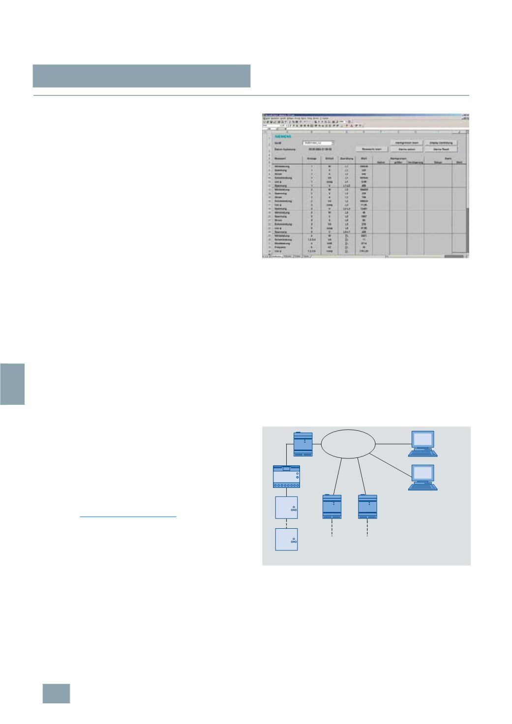
http://www.siemens.com/betaDisplay of measurement data on the PC
A Visual Basic macro for MS Excel is supplied with the LAN coupler
for the display of measurement data on a PC. Among other
things, this software tool lets you display all 35 measurement
data of a 7KT1 34 multicounter on a single panel. You can then
select the various measuring devices you want to display from a
small list box. The software also lets you set alarm limits for up to
10
measured quantities of a multicounter.
If a measured value exceeds or falls below the specified limits,
the relevant indication is output, complete with time stamp from
the PC clock.
Display of measurement data of a multicounter
Simultaneous display of measurement data on more than
one PC
The software supplied with the LAN coupler supports display of
measurement data on any number of PCs connected to the
network over a client-server architecture.
A PC acts as the server, similar to an Intranet or Internet server.
This PC runs the software components that retrieve the measurement
data from the LAN coupler and save it to hard disk. The MS Excel
macro can be used to visualize the measurement data on both
the server PC and the clients.
Other client PCs can access the data pool of the server PC to
visualize the measurement data.
Open software architecture
The architecture of the software tool is open and can be
customized to suit user requirements. The MS Excel macros are
freely accessible and can also be customized by the user.
Block diagram of a system
TCP/IP
network
PC Clients
-
Communication software
-
MS EXCEL visualization
-
Configuration tool (only
required for configuration of
the LAN coupler)
LAN coupler
Measuring
device 10
I201_13445
RS485
Measuring
device 2
LAN coupler
LAN coupler
Measuring
device 1
© Siemens AG 2008