


 439 / 582

BETA Measuring
Three-Phase Measuring Devices
7
KT1 1 E-counters instabus KNX
11/23
Siemens ET B1 · 10/2008
11
■
Overview
E-counters are used for the measurement of kWh in single- and
three-phase systems, e.g. in industrial plants, offices and
apartments in apartment houses. They help minimize operating
costs and facilitate cost assignment.
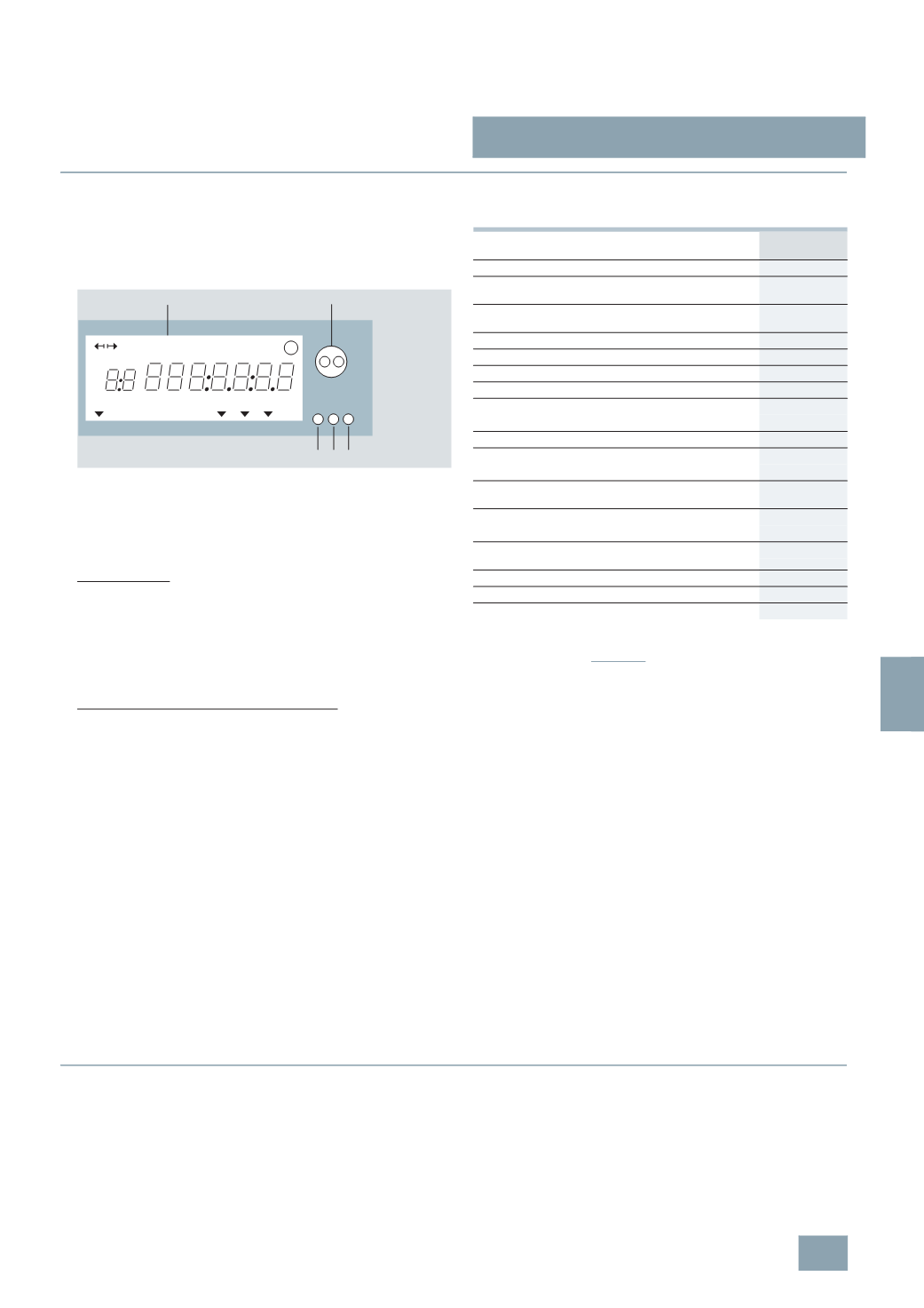
E-counter with LCD
1
Large-format 7-digit LCD 8 × 4 mm
2
IR readout interface for mounting the readout measuring head
3
Display pushbutton
4
IR test output LED (10 IMP./W)
5
Sealable Set/Reset pushbutton
Readout data for consumption analysis
Manual readout
The above data can be called up and manually displayed directly
on the E-counter by pressing pushbutton 5 (Set/Reset pushbutton)
and pushbutton 3 (Display pushbutton). The E-counter calculates
the consumption costs when the price per kWh has been entered.
The ability to input the device number facilitates assignment to a
number system and cost assignment to one of the various cost
centers.
Readout software for the IR measuring head
The data of the above table are read into a PC using the magnetic
IR measuring head and stored in an ASCII file according to
IEC 61107.
This ASCII file can be further processed in an Excel or Access file.
The product range can run under Windows 95, 98 and Windows NT.
Readout data on the LCD or over IR interface
x = data are displayed
Data transmission instabus KNX
The 7KT1 162 and 7KT1 165 counters are intended for the
following data transmission:
Active energy (kWh) rate 1
Active energy (kWh) rate 2
Device number
Active power (kW) phase L1
Active power (kW) phase L2
Active power (kW) phase L3
Visualization software "Recording of consumption data and
maximum time analysis" (available soon)
The software can read out and assign counter readings, and
prepare the data for accounting.
The system does not differentiate between counters that are
read out manually or in online operation.
A maximum time analysis can be carried out over several days
on the PC in online operation. Graphical analyses are also
available.
Energy flow direction
Counting is only carried out in the specified energy flow direction.
For counters with transformer connection, the energy flow
direction of the transformer (primary and secondary) as well as
the correct assignment of the voltage and current paths must be
taken into account.
■
Benefits
•
The devices have accuracy class 2. This enables extremely
precise energy measurements.
•
The large LCD for the reading out of all data locally makes for
easy reading.
+
1
3 4 5
2
PhQLT 1234
Hz
KUM MAX MkWArh
M
I2_07812a
7
KT1 162
7
KT1 165
Active energy
Rate 1/2
kWh x/x
Price per kWh
,
adjustable
Rate 1/2
Cost/
kWh
x/x
Total costs
Rate 1/2
Total
cost
x/x
Reactive energy
Rate 1/2
kvarh x/x
Apparent energy
Rate 1/2
kVAh --
Maximum active power
Rate 1/2
kW --
Integration periods,
adjustable
Rate 1/2
min --
Instantaneous active power
Sum total
kW x
Phase L1/L2/L3 kW x
Instantaneous voltage
Phase L1/L2/L3 V
--
Instantaneous imported kWh
Sum total
A
--
Phase L1/L2/L3 A
--
Instantaneous current factor
(
Only for transformer counters)
FA I
x
Instantaneous reactive power
Sum total
kvar
--
Phase L1/L2/L3 kvar
--
Instantaneous apparent power
Sum total
kVA --
Phase L1/L2/L3 kVA --
Instantaneous p.f.
Phase L1/L2/L3 p.f.
--
Instantaneous frequency
Hz
--
Device number
,
adjustable
No.
x
© Siemens AG 2008