


 438 / 582

BETA Measuring
Three-Phase Measuring Devices
7
KT1 5 E-counters
11/22
Siemens ET B1 · 10/2008
11
■
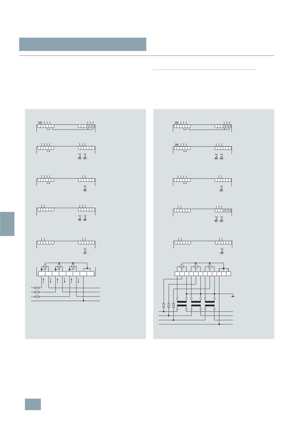
Schematics
Grounding terminal
The grounding terminals required for the transmission technology
for 7KT1 520 and 7KT1 521 versions only serve to shield the
transmission cables and do not have a protective function.
Rate switchover
If a voltage of 230 V AC is applied to terminals 4 and 5, the rate
is switched to rate 2.
Instructions for the connection of transformer counters
In the case of cross-section reduction, a short-circuit resistant
cable is required for the power supply of terminals L1, L2 and L3
depending on the fusing for phases L1, L2 and L3. A fuse of 6 A
is recommended for line protection.
Current transformers must not be operated with open terminals
as this can result in dangerously high voltages, which may result
in personal injuries and property damage. In addition to this, the
transformers are exposed to thermal overload.
I2_13492a
L1
L2
L3
L1 L1 L2 L2 L3 L3 N N
N
63
A
63
A
1 2 3 4 5
+ _
7
KT1 520
L N N L
2 3 4 5
7 8 9
7
KT1 512
L N N L
+ +–
2 3 4 5
8 9
7
KT1 510
L N N L
+–
2 3
7 8 9
7
KT1 502
L N
+ +–
2 3
8 9
7
KT1 500
L N
+–
63
A
230/400
V AC
Direct connection 63 A, 4-wire circuit
LAN
coupler
Shielding
230
V AC 230 V AC
Tariff
230
V AC 230 V AC
Tariff
2
x 5...30 V DC
230
V AC 230 V AC
Tariff
5...30
V DC
230
V AC
2
x 5...30 V DC
230
V AC
5...30
V DC
kWh
T1
kWh
T2
kWh
T1 - T2
kWh kvar
kWh T1
I2_13493a
2 3 4 5
8 9
7
KT1 511
L N N L
+–
2 3
8 9
7
KT1 501
L N
+–
2 3 4 5
+ _
7
KT1 521
L N N L
2 3 4 5
7 8 9
7
KT1 513
L N N L
+ +–
L1
L2
L3
6
A
1 2 3 4 5 6
7 8 9
7
KT1 503
L N
+ +–
N
k1 L1 l1 k2 L2 l2 k3 L3 l3 N N N
K
l
L
k
K
l
L
k
K
l
L
k
6
A 6 A
Shielding
5...30
V DC
5...30
V DC
2
x 5...30 V DC
2
x 5...30 V DC
LAN
coupler
Tariff
Tariff
Tariff
kWh
T1
kWh
T2
kWh
T1 - T2
kWh kvar
kWh T1
230/400
V AC
Current transformer connection, 4-wire circuit
230
V AC
230
V AC
230
V AC
230
V AC
230
V AC 230 V AC
230
V AC
230
V AC
© Siemens AG 2008