


 433 / 582

BETA Measuring
Three-Phase Measuring Devices
7
KT1 39 LAN couplers
11/17
Siemens ET B1 · 10/2008
*
You can order this quantity or a multiple thereof.
11
■
Selection and ordering data
■
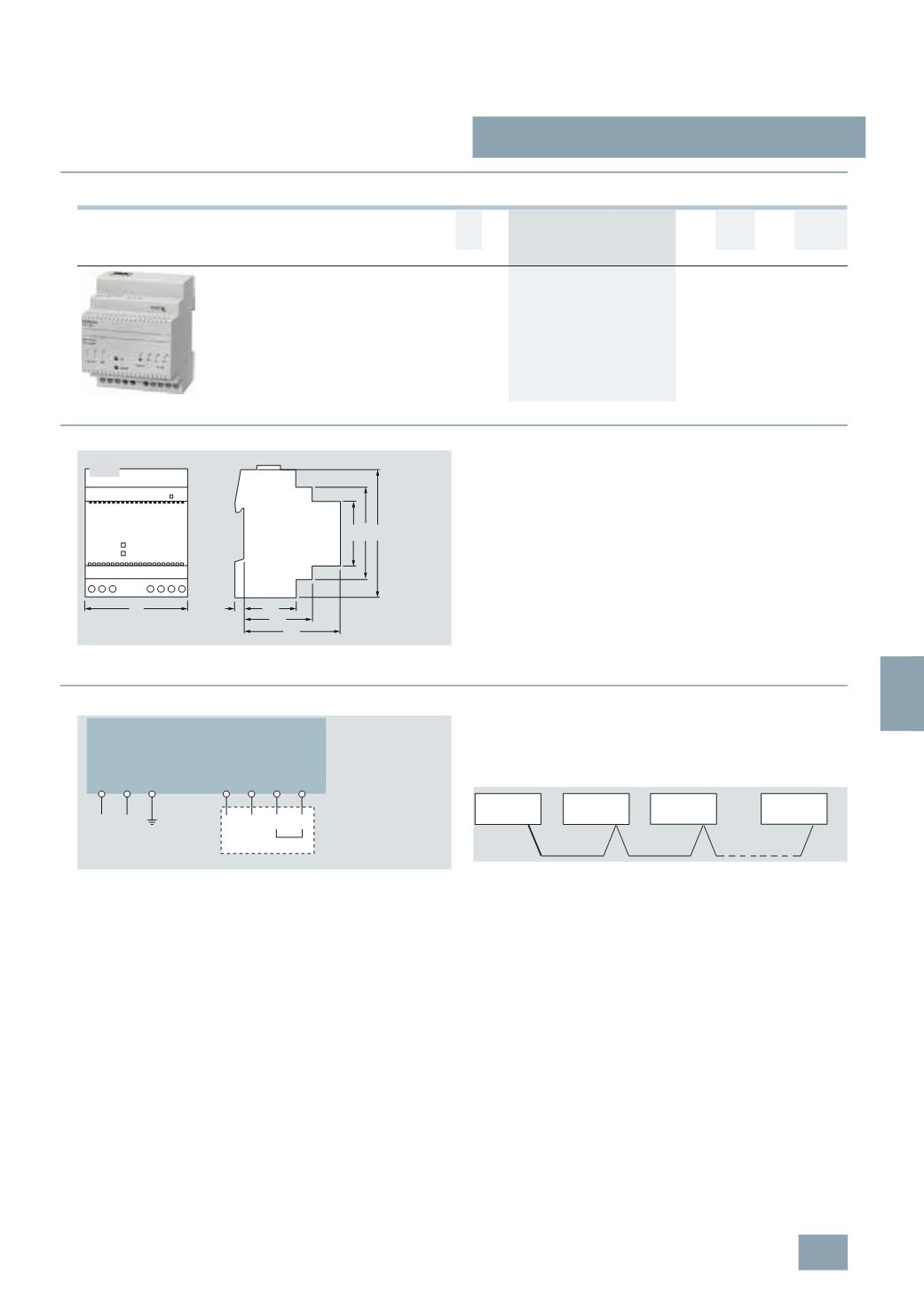
Dimensional drawings
■
Schematics
Connecting the devices to the LAN coupler
All the devices are connected in parallel with a shielded two-wire
cable. Point-to-point installations, junctions or ring installations
are not possible.
Grounding potential
Both the LAN cable with the RJ45 connector and the shielded
cable of the RS 485 bus system must be grounded. This also
applies to the devices connected to the LAN coupler.
U
c
MW DT Order No.
Price
per PU
PG PU PS*/
P. unit
Weight
per PU
approx.
V AC
Unit(s) Unit(s) kg
LAN couplers
For connection of up to 10 devices over RS485
Software tools included for:
•
Installation and commissioning
•
Data transmission and storage
•
MS Excel macro for visualization of measurement data
230
4
B
7
KT1 390
027 1
1
0.232
7
KT1 390
1 32
72
6 29
44
64
45
64
90
I2_11313b
987 10
RJ45
L N
1 2 3
7 8
RT D+ D-
9 10
I2_11414c
RJ45
RS 485
230
V AC
With shield
I2_11596b
Device 10
Device 1
Device 2
7
KT1 390
LAN coupler
© Siemens AG 2008