


 428 / 582

BETA Measuring
Three-Phase Measuring Devices
7
KT1 31, 7KT1 34, 7KT1 35 multicounters
11/12
Siemens ET B1 · 10/2008
11
■
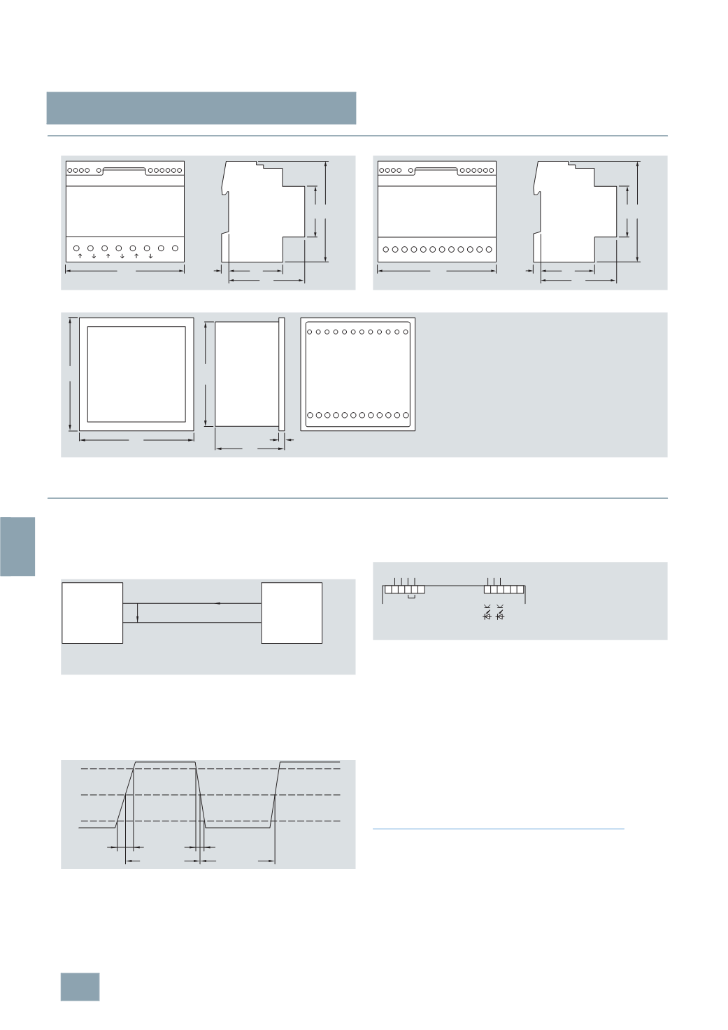
Dimensional drawings
■
Schematics
S0 interfaces
The S0 interface is a current interface for pulse transmission
between a counter with integral pulse generator device and tariff
rate device.
The tariff rate device is connected to the S0 interface of the
counter over a 2-wire conductor and – acting as a passive
electrical two-pole – supplies the pulse generator with a direct
voltage.
The following diagram shows the dependency of the current
path on the time according to DIN 43864.
The following diagram shows the pulse output (S0 interface) for
a 2-tariff counter:
e.g. tariff 1
>
normal tariff, tariff 2
>
special tariff.
For pulse recording with devices from other manufacturers
(
pulse counters or digital inputs), a voltage within the range of
5 ... 30
V DC must be applied to the output terminals of the S0
interface. The optocoupler operates as the switch. In order to
prevent overloading, the current must not exceed a max. of
20
mA.
The pulse duration is 125 ms. The minimum pulse interval is also
125
ms.
Grounding terminal
The interpolation point grounding terminals, required for the
transmission technology, only serve to shield the transmission
cables and do not have a protective function.
Instructions for the connection of transformer counters
In the case of cross-section reduction, a short-circuit resistant
cable is required for the power supply of terminals 2, 5 and 8,
depending on the fusing for phases L1, L2, L3. A fuse of 6 A is
recommended for the line protection.
Current transformers must not be operated with open terminals
as this can result in dangerously high voltages, which may result
in personal injuries and property damage. It can also lead to a
thermal overload of the transformers.
7
KT1 3.0
7
KT1 3.1
7
KT1 3.2
Rear panel
6
44
64
45
90
I2_11411a
1
108
2 3
L2 L1
L2 L3 L3
L1
N N
4 6
7 8 9 1011 12
6
44
64
45
90
I2_11412a
1
108
2 3
L2
L1
L3
k1
N
4 6
7 8 9 1011 12
l1 k2 l2 k3 l3
89,5
5
59
97
97
1 2 3 4 5 6 7 8 9 10 11 12
k1 l1 k2 l2 k3 l3
L2
L1
L3
N
I2_11514a
U
I
I2_12239a
U
:
Voltage at terminals of tariff device
I
:
Current via counter with integrated pulse generator
Counter with
integrated pulse
generator
Tariff device
t
A
≤ 5 ms
0,9
I
0,5
I
0,1
I
I2_12267a
t
1
≥ 30 ms
t
F
≤ 5 ms
t
2
≥ 30 ms
t
A
= Rise time
t
F
= Fall time
t
1
= Pulse
duration
t
2
= Pulse
interval
Off
On
7 8 9
L N N L
2 3 4 5
+ +–
I2_12268a
1 2
230
V AC
Tariff
Tariff
2
x S0 interface
2
x 5...30 V DC
© Siemens AG 2008