


 430 / 582

BETA Measuring
Three-Phase Measuring Devices
7
KT1 31, 7KT1 34, 7KT1 35 multicounters
11/14
Siemens ET B1 · 10/2008
11
■
More information
Communication interfaces
Multicounters with PROFIBUS interface
Multicounters are also available with PROFIBUS interface. In a
PROFIBUS network, the multicounters act as PROFIBUS DP
slave according to the usual standard V0 (cyclic communication
only).
In a PROFIBUS network, several PROFIBUS slaves are always
assigned to a single master. A PC with a PROFIBUS communication
module or PLC, such as the PLCs of the SIMATIC range from
Siemens, can be used as the master. The master communicates
with the connected slaves cyclically at extremely brief intervals.
The master sends the slaves a request message to which the
slave replies with a response message. The communication
frame of the message (e.g. number of send and receive bytes)
is slave-specific and is defined in a standardized text file; the
device data base file (DDBF). This DDBF file is read in by the
software configuration tools of the various PROFIBUS masters,
whereby the master knows which communication frame the
respective slave requires.
In normal cyclic mode, the multicounter sends a response
message in the specified communication frame in reply to the
request message from the master. This communication frame
contains all 35 measured quantities in encoded form as user
data. The master receives the message, decodes it and then
uses the measurement data for a range of tasks.
As well as the DDBF file, a detailed description of the communication
and the configuration of the user data are also required for the
configuration and implementation of a PROFIBUS network with
multicounters. For more information please visit us on the
Internet at:
http://www.siemens.com/betaMulticounters with Modbus interface
The Modbus RTU is a very common communications solution. It
is a serial, asynchronous form of communication, which requires
RS 485 networks as the hardware platform. RS 485 networks can
be set up with 2-wire copper or optical fiber cables and, compared
to the RS 232 serial interface, offer fast transmission rates.
In a Modbus network, each bus station has a bus address within
the range from 1 to 255. All stations within a network must be set
to the same transmission rate. We recommend transmission
speeds of 9600 or 19200 bit/s. The address and transmission
speed can be set in the user menu of the multicounters.
In order to customize a Modbus installation, it is necessary to
implement the appropriate software application for the master.
This requires specific information about communication with
multicounters. For more information please visit us on the
Internet at:
http://www.siemens.com/betaMulticounters with LAN coupler on LAN
The 7KT1 390 LAN couplers support connection of up to
ten 7KT1 34 multicounters to a LAN network. The LAN couplers
and multicounters are interlinked over an RS 485 network.
Setting the bus address in the 7KT1 34 multicounters to "0"
specifies that it is operating in "LAN" mode. It is not necessary to
set the transmission speed, as a fixed transmission rate is always
used in this mode. It is also not necessary to set the address of
the bus stations, as the LAN coupler automatically detects and
identifies the multicounter connected.
The server components run on the PC in the background and
handle the data transmission and storage of the most recent
measured values from all the multicounters connected over one
or more LAN couplers.
For more information on LAN operation and the MS E
xcel
operator
interface, see 7KT1 390 LAN couplers
on page 11/16 ff.
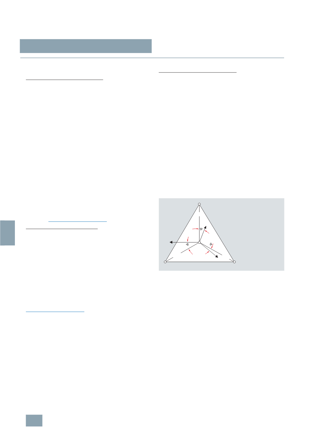
Voltage measurement
Depending on the selected connection type, the multicounter
measures the delta voltages L1 against L2; L2 against L3 and L3
against L1 or the star voltages L1, L2, L3 against N.
L symbol for the 3-phase system
This indicates that all physical units shown under this symbol are
always 3-phase.
Temperature
The temperature indication of the multicounter is not suitable for
an exact measurement of the ambient temperature. The device
does not have a temperature sensor. It is also not possible to
connect an external temperature sensor.
The temperature information merely enables a rough estimate of
the temperature conditions in the device interior and immediate
surroundings.
l1
L1-N
L1-L2
L1
L2
L3
L3-L1
l2
l3
L3-N
L2-N
N
L2-L3
I2_08410b
1
2
3
© Siemens AG 2008