


 84 / 253

12/42
Control relays, multi-function display
Basic devices, expansion devices
...T..., MFD...T...
2010
CA08103002Z-EN
www.eaton.com...T...,MFD...T...Basicdevices,expansiondevices
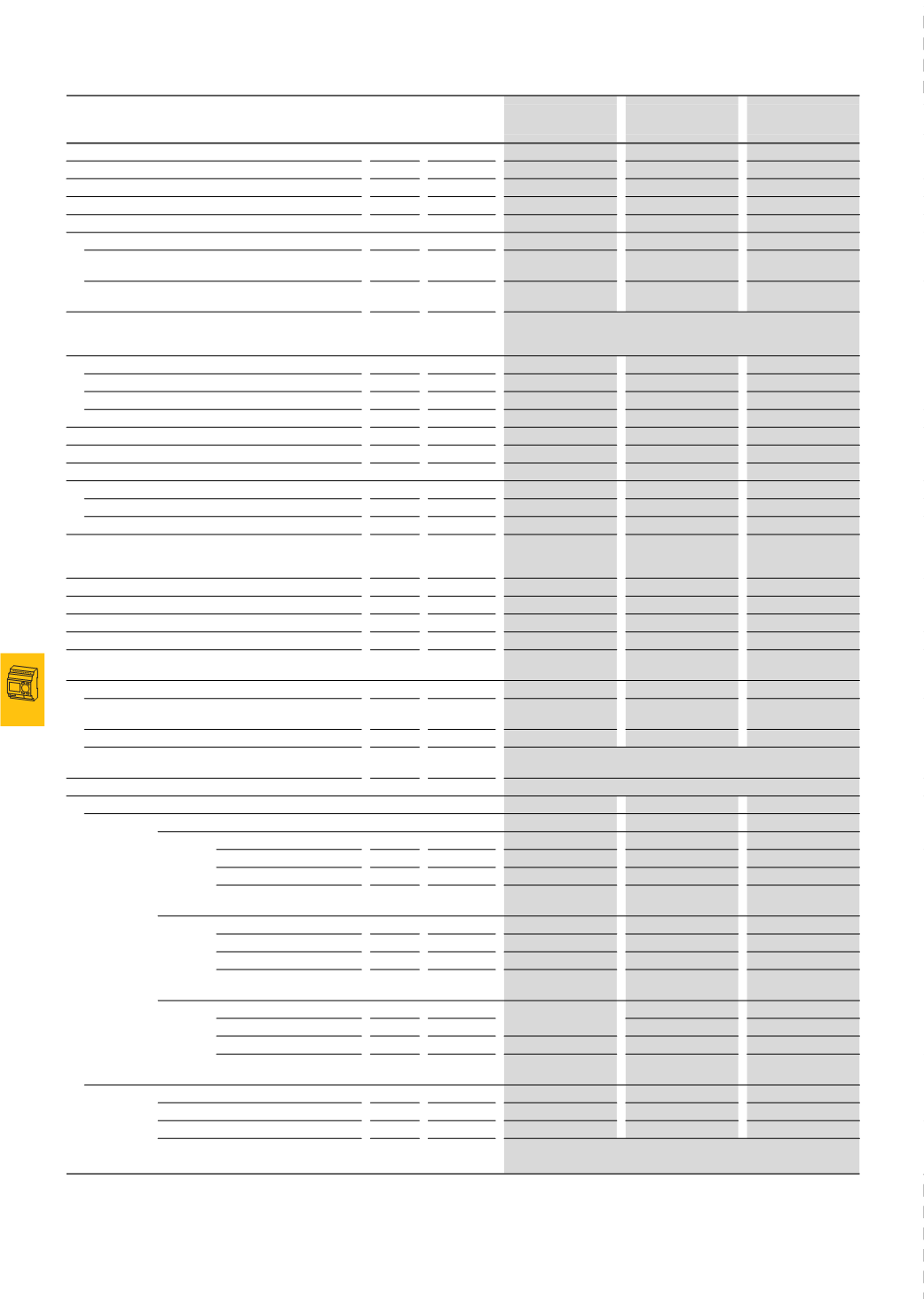
EASY4…-DC-ME
EASY512-DC-T..
EASY410-DC-TE
EC4E-221-DT…
Transistor outputs
Number
2
4
4
Rated operating voltage
U
e
V DC
24
24
24
Permissible range
U
e
V DC
20.4 - 28.8
20.4 - 28.8
20.4 - 28.8
Ripple
%
≦ 5
≦ 5
≦ 5
Supply current
On signal ”0”
Normally⁄
max.
mA
24
V/2A
9/16
9/16
On signal ”1”
Normally⁄
max.
mA
12/22
12/22
12/22
Protection against polarity reversal
Yes (Caution: A short circuit will result if 0 V or GND is applied to the
outputs in the event that the supply voltage is connected to the wrong
poles.)
Potential isolation
Potential isolation from power supply, inputs
No
Yes
Yes
From PC interface, memory card, easyNet, easyLink
Yes
Yes
Yes
From the inputs
–
–
–
Rated operational current on signal "1" DC
I
e
A
1
Max. 0.5
Max. 0.5
Lamp load without R
v
W
5
5
5
Residual current on signal "0" per channel
mA
< 0.1
< 0.1
< 0.1
Max. output voltage
On "0" at external load < 10 MΩ
V
2.5
2.5
2.5
On “1” at I
e
= 0.5 A
V
U = U
e
-1
V
U = U
e
-1
V
U = U
e
-1
V
Short-circuit protection
Yes, thermal (analysis
via diagnostics input
R16)
Yes, thermal (analysis
via diagnostics input
I16, I15; R15, R16)
Yes, thermal (analysis
via diagnostics input
R16)
Short-circuit tripping current for R
a
≦ 10 mΩ
A
1.4
≦ I
e
≦ 4
0.7
≦ I
e
≦ 2 per output 0.7 ≦ I
e
≦ 2 per output
Total short-circuit current
A
8
8
8
Peak short-circuit current
A
16
16
16
Thermal cutout
Yes
Yes
Yes
Max. operating frequency at constant resistive load
R
L
< 100 kΩ (dependent on program and load)
Ops/h
40000
40000
40000
Parallel connection of outputs
With resistive load, inductive load with external
suppressor circuit, combination within a group
Q1 and Q2
Group 1: Q1 to Q4
Group 1: Q1 to Q4
Number of outputs
Max.
2
4
4
Max. total current
A
2 (
Attention! Outputs must be activated simultaneously and for the same
duration)
Status indication of the outputs
LCD display (if provided)
Inductive load to EN 60947-5-1
Without external suppressor circuit
T
0.95
= 1 ms, R = 48 Ω, L = 16 mH
Utilization factor
g
0.25
0.25
0.25
Duty factor
%
DF
100
100
100
Max. operating frequency
f = 0.5 Hz (max. ED = 50 %)
Operations 1500
1500
1500
DC-13, T
0.95
= 72 ms, R = 48 Ω, L = 1.15 H
Utilization factor
g
0.25
0.25
0.25
Duty factor
%
DF
100
100
100
Max. operating frequency
f = 0.5 Hz (max. ED = 50 %)
Operations 1500
1500
1500
T
0.95
= 15 ms, R = 48 Ω, L = 0.24 H
Utilization factor
g
0.25
0.25
0.25
Duty factor
%
DF
100
100
100
Max. operating frequency
f = 0.5 Hz (max. ED = 50 %)
Operations 1500
1500
1500
With external suppressor circuit
Utilization factor
g
1
1
1
Duty factor
%
DF
100
100
100
Max. switching frequency, max.
duty factor
Operations Depending on the suppressor circuit
Notes
For additional technical data EASY5… and EASY7…→AWB2528-1508D, EASY8…
→AWB2528-1423D, MFD-Titan→AWB2528-1480D