


 276 / 300

Furse, Wilford Road, Nottingham, NG2 1EB • Tel: +44 (0)115 964 3700 • Email:
enquiry@furse.com• Web:
www.furse.comTSC-0912 - 09.10.12
Guide to BS EN/IEC 62305
BS EN/IEC 62305-3
Non-conventional air
termination systems
A lot of technical (and commercial) debate has raged
over the years regarding the validity of the claims
made by the proponents of such systems.
This topic was discussed extensively within
the technical working groups that compiled
BS EN/IEC 62305. The outcome was to remain with
the information housed within this standard.
BS EN/IEC 62305 states unequivocally that the volume
or zone of protection afforded by the air termination
system (e.g. air rod) shall be determined only by the
real physical dimension of the air termination system.
This statement is reinforced within the 2011 version of
BS EN 62305, by being incorporated in the body of the
standard, rather than forming part of an Annex
(Annex A of BS EN/IEC 62305-3:2006).
Typically if the air rod is 5 m tall then the only claim for
the zone of protection afforded by this air rod would
be based on 5 m and the relevant class of LPS and not
any enhanced dimension claimed by some non-
conventional air rods.
There is no other standard being contemplated to run
in parallel with this standard BS EN/IEC 62305.
Natural components
When metallic roofs are being considered as a natural
air termination arrangement, then BS 6651 gave
guidance on the minimum thickness and type of
material under consideration.
BS EN/IEC 62305-3 gives similar guidance as well as
additional information if the roof has to be
considered puncture proof from a lightning discharge
(see Table 10).
The mesh method
This is the method that was most commonly used
under the recommendations of BS 6651. Again, within
BS EN/IEC 62305 four different air termination mesh
sizes are defined and correspond to the relevant class
of LPS (see Table 9).
This method is suitable where plain surfaces require
protection if the following conditions are met:
Air termination conductors must be positioned at
roof edges, on roof overhangs and on the ridges of
roof with a pitch in excess of 1 in 10 (5.7º)
No metal installation protrudes above the air
termination system
Modern research on lightning inflicted damage has
shown that the edges and corners of roofs are most
susceptible to damage.
So on all structures particularly with flat roofs,
perimeter conductors should be installed as close to
the outer edges of the roof as is practicable.
As in BS 6651, the current standard permits the use of
conductors (whether they be fortuitous metalwork or
dedicated LP conductors) under the roof. Vertical air
rods (finials) or strike plates should be mounted above
the roof and connected to the conductor system
beneath. The air rods should be spaced not more than
10 m apart and if strike plates are used as an
alternative, these should be strategically placed over
the roof area not more than 5 m apart.
Class of LPS
Mesh size
(m)
I
5 x 5
II
10 x 10
III
15 x 15
IV
20 x 20
Table 9: Maximum values of mesh size corresponding to
the Class of LPS
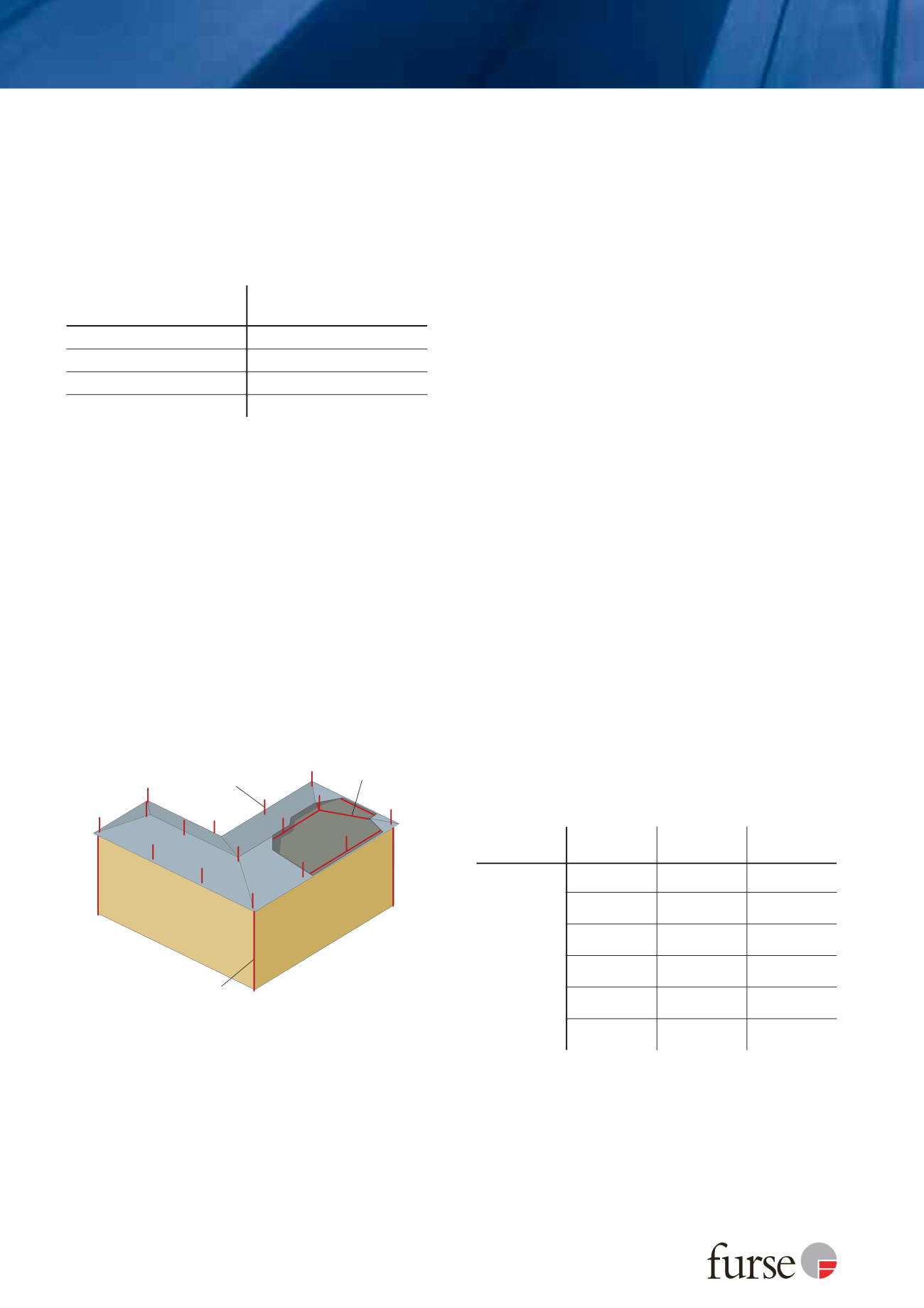
Figure 19: Concealed air termination network
Concealed
conductor
Vertical air
termination
Down conductor
Class of LPS
Material
Thickness
(1)
t (mm)
Thickness
(2)
t’ (mm)
I to IV
Lead
-
2.0
Steel (stainless,
galvanized)
4
0.5
Titanium
4
0.5
Copper
5
0.5
Aluminium
7
0.65
Zinc
-
0.7
Table 10: Minimum thickness of metal sheets or metal pipes in air
termination systems (BS EN/IEC 62305-3 Table 3)
(1) Thickness t prevents puncture, hot spot or ignition.
(2) Thickness t’ only for metal sheets if it is not important to prevent
puncture, hot spot or ignition problems.