


 279 / 300

Furse, Wilford Road, Nottingham, NG2 1EB • Tel: +44 (0)115 964 3700 • Email:
enquiry@furse.com• Web:
www.furse.comTSC-0912 - 09.10.12
BS EN/IEC 62305-3
Guide to BS EN/IEC 62305
Internal LPS design considerations
The fundamental role of the internal LPS is to ensure
the avoidance of dangerous sparking occurring within
the structure to be protected. This could be due,
following a lightning discharge, to lightning current
flowing in the external LPS or indeed other conductive
parts of the structure and attempting to flash or spark
over to internal metallic installations.
Carrying out appropriate equipotential bonding
measures or ensuring there is a sufficient electrical
insulation distance between the metallic parts can
avoid dangerous sparking between different
metallic parts.
Lightning equipotential bonding
Equipotential bonding is simply the electrical
interconnection of all appropriate metallic
installations/parts, such that in the event of lightning
currents flowing, no metallic part is at a different
voltage potential with respect to one another. If the
metallic parts are essentially at the same potential then
the risk of sparking or flashover is nullified.
This electrical interconnection can be achieved by
natural/fortuitous bonding or by using specific
bonding conductors that are sized according to Tables
8 and 9 of BS EN/IEC 62305-3.
Bonding can also be accomplished by the use of surge
protective devices (SPDs) where the direct connection
with bonding conductors is not suitable.
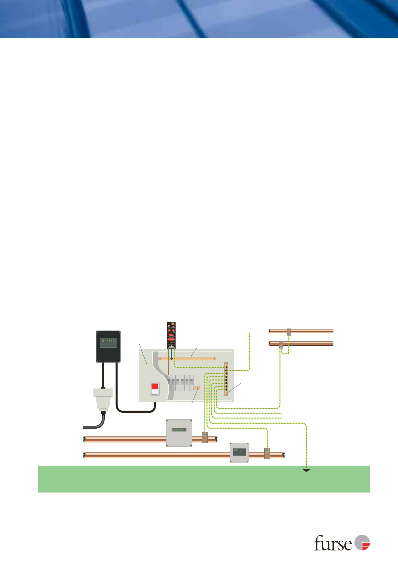
Figure 21 (which is based on BS EN/IEC 62305-3 fig
E.43) shows a typical example of an equipotential
bonding arrangement. The gas, water and central
heating system are all bonded directly to the
equipotential bonding bar located inside but close to
an outer wall near ground level. The power cable is
bonded via a suitable SPD, upstream from the electric
meter, to the equipotential bonding bar. This bonding
bar should be located close to the main distribution
board (MDB) and also closely connected to the earth
termination system with short length conductors. In
larger or extended structures several bonding bars may
be required but they should all be interconnected with
each other.
The screen of any antenna cable along with any
shielded power supply to electronic appliances being
routed into the structure should also be bonded at the
equipotential bar.
Further guidance relating to equipotential bonding,
meshed interconnection earthing systems and SPD
selection can be found in the Furse guidebook.
Figure 21: Example of main equipotential bonding
Equipotential
bonding bar
Structural lightning
protection system
Central heating system
Screen of antenna cable
Electronic appliances
Power from utility
Meter
Meter
Gas
Water
Electricity
meter
Consumer unit/
fuseboard
SPD
ON
OFF
Neutral bar
Live bar
N