


 277 / 300

Furse, Wilford Road, Nottingham, NG2 1EB • Tel: +44 (0)115 964 3700 • Email:
enquiry@furse.com• Web:
www.furse.comTSC-0912 - 09.10.12
BS EN/IEC 62305-3
Guide to BS EN/IEC 62305
can be decided at the early construction stage by using
dedicated reinforcing bars or alternatively to run a
dedicated copper conductor from the top of the
structure to the foundation prior to the pouring of the
concrete. This dedicated copper conductor should be
bonded to the adjoining/adjacent reinforcing bars
periodically.
If there is doubt as to the route and continuity of the
reinforcing bars within existing structures then an
external down conductor system should be installed.
These should ideally be bonded into the reinforcing
network of the structures at the top and bottom of
the structure.
Down conductors
Down conductors should within the bounds of
practical constraints take the most direct route from
the air termination system to the earth termination
system. The greater the number of down conductors
the better the lightning current is shared between
them. This is enhanced further by equipotential
bonding to the conductive parts of the structure.
Lateral connections sometimes referred to as coronal
bands or ring conductors provided either by fortuitous
metalwork or external conductors at regular intervals
are also encouraged. The down conductor spacing
should correspond with the relevant class of LPS (see
Table 11).
There should always be a minimum of two down
conductors distributed around the perimeter of the
structure. Down conductors should wherever possible
be installed at each exposed corner of the structure as
research has shown these to carry the major part of the
lightning current.
Natural components
BS EN/IEC 62305, like BS 6651, encourages the use of
fortuitous metal parts on or within the structure to be
incorporated into the LPS.
Where BS 6651 encouraged an electrical continuity when
using reinforcing bars located in concrete structures, so
too does BS EN/IEC 62305-3. Additionally, it states that
reinforcing bars are welded, clamped with suitable
connection components or overlapped a minimum of 20
times the rebar diameter. This is to ensure that those
reinforcing bars likely to carry lightning currents have
secure connections from one length to the next.
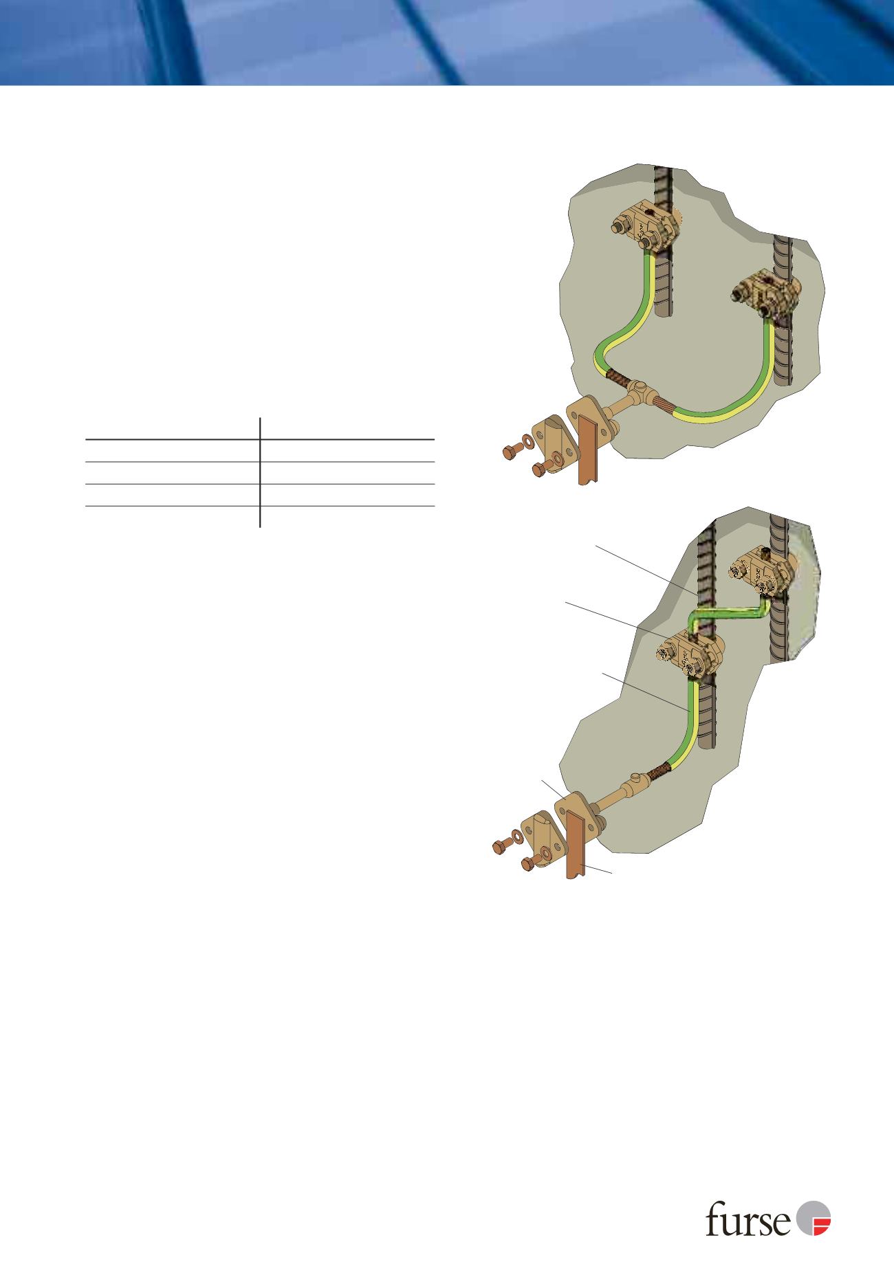
When internal reinforcing bars are required to be
connected to external down conductors or earthing
network either of the arrangements shown in
Figure 20 is suitable. If the connection from the
bonding conductor to the rebar is to be encased in
concrete then the standard recommends that two
clamps are used, one connected to one length of rebar
and the other to a different length of rebar. The joints
should then be encased by a moisture inhibiting
compound such as Denso tape.
If the reinforcing bars (or structural steel frames) are to
be used as down conductors then electrical continuity
should be ascertained from the air termination system
to the earthing system. For new build structures this
Class of LPS
Typical distances (m)
I
10
II
10
III
15
IV
20
Table 11: Typical values of the distance between down conductors
according to the Class of LPS (BS EN/IEC 62305-3 Table 4)
Figure 20: Typical methods of bonding to steel reinforcement
within concrete
Stranded copper cable
(70 mm
2
PVC insulated)
Cast in
non−ferrous
bonding
point
Bonding conductor
Clamped cable to rebar
connection
Steel reinforcement within
concrete (rebar)