


 148 / 356

B-10
Distribution
Busbar calculation
Linergy
busbars
Cat. no.
Permissible
current
at 35 °C
for switchboard
No. of supports
Icw
(kA rms / 1 s)
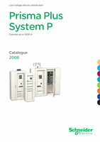
The table opposite indicates:
b
the catalogue numbers of the bars to be used,
depending on the permissible current level in the
busbars
b
the number of supports required, depending on the
rated short-time withstand current (Icw in kA rms / 1
second).
Above 1600 A, the busbars must be doubled and
installed in two busbar sections, side by side. In this
case, they must be interconnected by three
equipotential links.
For more information on other ambient temperatures,
see page D-24.
IP
y
31 IP > 31
y
25
y
30
y
40
y
50
y
60
y
65
y
75
y
85
Linergy 630
04502
680 590
Linergy 800
04503
840 760
Linergy 1000
04504
1040 950
3
Linergy 1250
04505
1290 1170
4 5
Linergy 1600
04506
1650 1480
7 8
Double busbars
Linergy 2000
04504 x 2
2000 1820
Linergy 2500
04505 x 2
2500 2260
2 x 3
2 x 4 2 x 5
Linergy 3200
04506 x 2
3200 2920
Note:
The permissible current values for the busbars are given for an ambient temperature of
35°C around the switchboard.
The bottom support also maintains the bars in position.
Each catalogue number represents one bar.
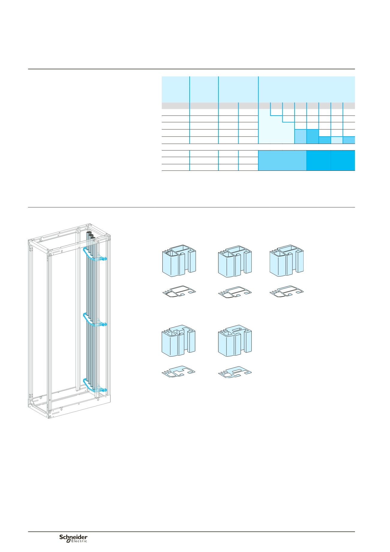
Busbar selection
Linergy busbars, L = 1670 mm
Cat. no. selection
See the table below.
Each bar is supplied with a stop for the bottom support.
DD381232
DD381233
DD381234
DD381235
Bar 630 A.
Cat. no. 04502
Bar 800 A.
Cat. no. 04503
Bar 1000 A.
Cat. no. 04504
DD381236
DD381237
Bar 1250 A.
Cat. no. 04505
Bar 1600 A.
Cat. no. 04506
Busbars up to 1600 A.
The bottom support also maintains the bars in position.
Lateral Linergy busbars
up to 3200 A
Main distribution