


 256 / 338

D-22
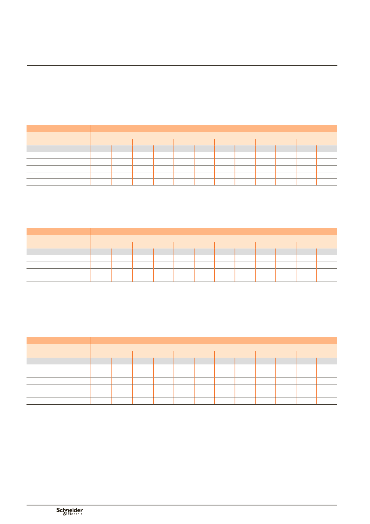
Permissible current and selection of vertical busbar
The goal is to optimise busbar size according to the installation and
operating criteria.
Up to 1600 A
Linergy LGY section
Type of bars
Permissible current (A)
Ambient temperature around the switchboard
25 °C
30 °C
35 °C
40 °C
45 °C
50 °C
IP
y
31 IP > 31 IP
y
31 IP > 31 IP
y
31 IP > 31 IP
y
31 IP > 31 IP
y
31 IP > 31 IP
y
31 IP > 31
Linergy LGY 630
750
680
710
630
680
590
630
550
590
530
550
bb
Linergy LGY 800
920
840
880
800
840
760
800
720
760
680
720
bb
Linergy LGY 1000
1140 1040 1090 990
1040 950
990
900
950
850
900
bb
Linergy LGY 1250
1410 1290 1350 1230 1290 1170 1230 1100 1170 1050 1100
bb
Linergy LGY 1600
1800 1650 1720 1580 1650 1480 1580 1390 1480 1320 1390
bb
bb
Connection impossible due to the operating-temperature limits of the devices installed in the switchboard.
Up to 1600 A
Linergy BS bars, 5 mm thick
Type of bars
Permissible current (A)
Ambient temperature around the switchboard
25 °C
30 °C
35 °C
40 °C
45 °C
50 °C
Size per phase
IP
y
31 IP > 31 IP
y
31 IP > 31 IP
y
31 IP > 31 IP
y
31 IP > 31 IP
y
31 IP > 31 IP
y
31 IP > 31
1 Linergy BS bar, 60 x 5
890
840
850
790
800
750
760
700
710
650
660
bb
1 Linergy BS bar, 80 x 5
1130 1050 1080 990
1000 900
970
870
910
810
860
bb
2 Linergy BS bars, 60 x 5
1580 1420 1500 1350 1400 1250 1350 1180 1260 1090 1180
bb
2 Linergy BS bars, 80 x 5
2010 1820 1920 1720 1800 1600 1720 1510 1610 1390 1510
bb
bb
Connection impossible due to the operating-temperature limits of the devices installed in the switchboard.
Up to 3200 A
Linergy BS bars, 10 mm thick
Type of bars
Permissible current (A)
Ambient temperature around the switchboard
25 °C
30 °C
35 °C
40 °C
45 °C
50 °C
Size per phase
IP
y
31 IP > 31 IP
y
31 IP > 31 IP
y
31 IP > 31 IP
y
31 IP > 31 IP
y
31 IP > 31 IP
y
31 IP > 31
1 Linergy BS bar, 50 x 10
1330 1220 1260 1160 1200 1080 1130 1010 1060 940
990
bb
1 Linergy BS bar, 60 x 10
1550 1400 1470 1320 1400 1250 1320 1160 1240 1070 1160
bb
1 Linergy BS bar, 80 x 10
1990 1800 1890 1700 1800 1600 1700 1500 1600 1390 1500
bb
2 Linergy BS bars, 80 x 10
2270 2090 2160 1980 2050 1850 1930 1740 1810 1610 1690
bb
2 Linergy BS bars, 60 x 10
2550 2270 2420 2140 2300 2000 2170 1870 2030 1720 1900
bb
2 Linergy BS bars, 80 x 10
3110 2820 2970 2660 2820 2500 2660 2330 2500 2160 2330
bb
bb
Connection impossible due to the operating-temperature limits of the devices installed in the switchboard.
Note:
the values indicated above have been validated for Prisma P switchboards.
Additional information
Electrical characteristics
Designing rear busbars
Linergy LGYE, Linergy BS