


 261 / 338

D-27
Additional information
Electrical characteristics
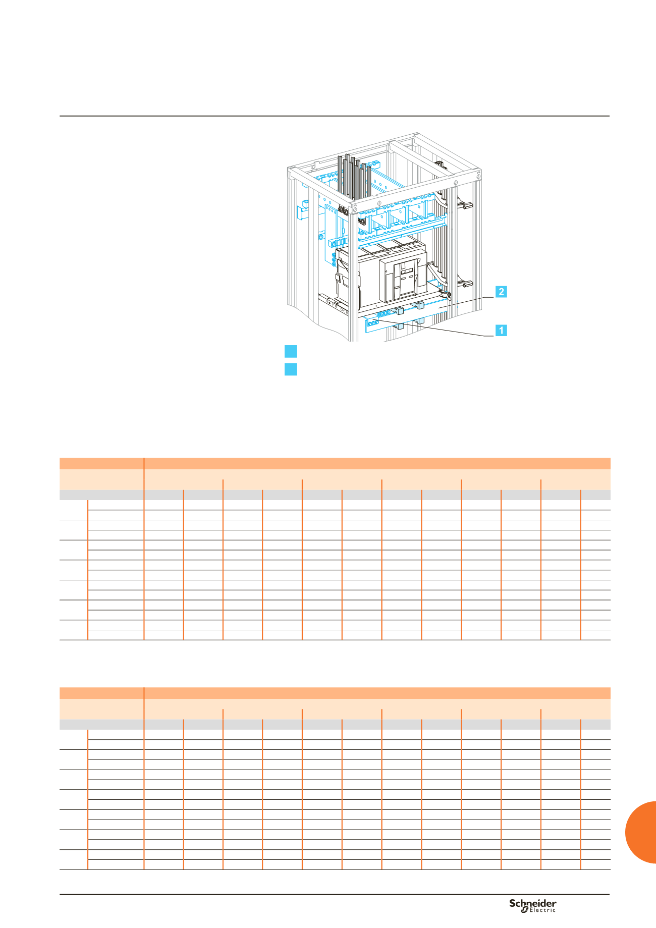
Masterpact NW08 to NW32
Fixed
Vertical busbars on the left or right
Linergy LGYE, LGY, BS busbars
Connections drawings supplied by
Schneider Electric
Dd383668.eps
1
Connection.
2
Horizontal link.
Using the data below, it is possible to determine the size of the copper bars and the
maximum permissible currents when making the connections to busbars for a
vertical, fixed Masterpact NW08/NW32, front or rear connection, taking into account
the ambient temperature around the switchboard and the IP value.
Connection
Flat bars, 10 mm thick
Device
Permissible current (A)
Ambient temperature around the switchboard
25 °C
30 °C
35 °C
40 °C
45 °C
50 °C
IP
y
31 IP > 31 IP
y
31 IP > 31 IP
y
31 IP > 31 IP
y
31 IP > 31 IP
y
31 IP > 31 IP
y
31 IP > 31
NW08 Size per phase 1b 80 x 10 1b 80 x 10 1b 80 x 10 1b 80 x 10 1b 80 x 10 1b 80 x 10 1b 80 x 10 1b 80 x 10 1b 80 x 10 1b 80 x 10 1b 80 x 10
bb
I (A)
800
800
800
800
800
800
800
800
800
800
800
NW10 Size per phase 1b 80 x 10 1b 80 x 10 1b 80 x 10 1b 80 x 10 1b 80 x 10 1b 80 x 10 1b 80 x 10 1b 80 x 10 1b 80 x 10 1b 80 x 10 1b 80 x 10
bb
I (A)
1000
1000
1000
1000
1000
1000
1000
1000
1000
1000
1000
NW12 Size per phase 1b 80 x 10 1b 80 x 10 1b 80 x 10 1b 80 x 10 1b 80 x 10 1b 80 x 10 1b 80 x 10 1b 80 x 10 1b 80 x 10 1b 80 x 10 1b 80 x 10
bb
I (A)
1250
1250
1250
1250
1250
1250
1250
1250
1250
1250
1250
NW16 Size per phase 1b 80 x 10 1b 80 x 10 1b 80 x 10 1b 80 x 10 1b 80 x 10 1b 80 x 10 1b 80 x 10 1b 80 x 10 1b 80 x 10 1b 80 x 10 1b 80 x 10
bb
I (A)
1600
1600
1600
1570
1600
1520
1570
1470
1520
1420
1470
NW20 Size per phase 2b 80 x 10 2b 80 x 10 2b 80 x 10 2b 80 x 10 2b 80 x 10 2b 80 x 10 2b 80 x 10 2b 80 x 10 2b 80 x 10 2b 80 x 10 2b 80 x 10
bb
I (A)
2000
2000
2000
2000
2000
2000
2000
1950
2000
1900
1950
NW25 Size per phase 2b 80 x 10 2b 80 x 10 2b 80 x 10 2b 80 x 10 2b 80 x 10 2b 80 x 10 2b 80 x 10 2b 80 x 10 2b 80 x 10 2b 80 x 10 2b 80 x 10
bb
I (A)
2500
2500
2500
2500
2500
2460
2500
2380
2500
2300
2460
NW32 Size per phase 3b 80 x 10 3b 80 x 10 3b 80 x 10 3b 80 x 10 3b 80 x 10 3b 80 x 10 3b 80 x 10 3b 80 x 10 3b 80 x 10 3b 80 x 10 3b 80 x 10
bb
I (A)
3200
3000
3170
2910
3080
2820
3000
2730
2910
2630
2820
bb
Connection impossible due to the operating-temperature limits of the devices installed in the switchboard.
Horizontal link
Flat bars, 10 mm thick
Device
Permissible current (A)
Ambient temperature around the switchboard
25 °C
30 °C
35 °C
40 °C
45 °C
50 °C
IP
y
31 IP > 31 IP
y
31 IP > 31 IP
y
31 IP > 31 IP
y
31 IP > 31 IP
y
31 IP > 31 IP
y
31 IP > 31
NW08 Size per phase 1b 60 x 10 1b 60 x 10 1b 60 x 10 1b 60 x 10 1b 60 x 10 1b 60 x 10 1b 60 x 10 1b 60 x 10 1b 60 x 10 1b 60 x 10 1b 60 x 10
bb
I (A)
800
800
800
800
800
800
800
800
800
800
800
NW10 Size per phase 1b 60 x 10 1b 60 x 10 1b 60 x 10 1b 60 x 10 1b 60 x 10 1b 60 x 10 1b 60 x 10 1b 60 x 10 1b 60 x 10 1b 60 x 10 1b 60 x 10
bb
I (A)
1000
1000
1000
1000
1000
1000
1000
1000
1000
1000
1000
NW12 Size per phase 1b 60 x 10 1b 60 x 10 1b 60 x 10 1b 60 x 10 1b 60 x 10 1b 60 x 10 1b 60 x 10 1b 60 x 10 1b 60 x 10 1b 60 x 10 1b 60 x 10
bb
I (A)
1250
1250
1250
1250
1250
1250
1250
1250
1250
1250
1250
NW16 Size per phase 1b 80 x 10 1b 80 x 10 1b 80 x 10 1b 80 x 10 1b 80 x 10 1b 80 x 10 1b 80 x 10 1b 80 x 10 1b 80 x 10 1b 80 x 10 1b 80 x 10
bb
I (A)
1600
1600
1600
1570
1600
1520
1570
1470
1520
1420
1470
NW20 Size per phase 2b 60 x 10 2b 60 x 10 2b 60 x 10 2b 60 x 10 2b 60 x 10 2b 60 x 10 2b 60 x 10 2b 60 x 10 2b 60 x 10 2b 60 x 10 2b 60 x 10
bb
I (A)
2000
2000
2000
2000
2000
2000
2000
1950
2000
1900
1950
NW25 Size per phase 2b 80 x 10 2b 80 x 10 2b 80 x 10 2b 80 x 10 2b 80 x 10 2b 80 x 10 2b 80 x 10 2b 80 x 10 2b 80 x 10 2b 80 x 10 2b 80 x 10
bb
I (A)
2500
2500
2500
2500
2500
2460
2500
2380
2500
2300
2460
NW32 Size per phase 2b100x10 2b100x10 2b100x10 2b100x10 2b100x10 2b100x10 2b100x10 2b100x10 2b100x10 2b100x10 2b100x10
bb
I (A)
3200
3000
3170
2910
3080
2820
3000
2730
2910
2630
2820
bb
Connection impossible due to the operating-temperature limits of the devices installed in the switchboard.
Note:
the values indicated above have been validated for Prisma P switchboards.
Designing connections between
a device and busbars
Fixed Masterpact NW08 to NW32