


 263 / 338

D-29
Additional information
Electrical characteristics
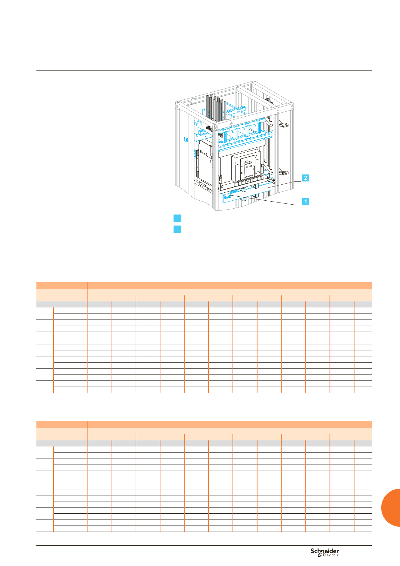
Masterpact NW08 à NW32
Drawout
Vertical busbars on the left or right
Linergy LGYE, LGY, BS busbars
Connections drawings supplied by
Schneider Electric
Dd383670.eps
1
Connection.
2
Horizontal link.
Using the data below, it is possible to determine the size of the copper bars and the
maximum permissible currents when making the connections to busbars for a
vertical, drawout Masterpact NW08/NW32, front or rear connection, taking into
account the ambient temperature around the switchboard and the IP value.
Connection
Flat bars, 10 mm thick
Device
Permissible current (A)
Ambient temperature around the switchboard
25 °C
30 °C
35 °C
40 °C
45 °C
50 °C
IP
y
31 IP > 31 IP
y
31 IP > 31 IP
y
31 IP > 31 IP
y
31 IP > 31 IP
y
31 IP > 31 IP
y
31 IP > 31
NW08 Size per phase 1b 80 x 10 1b 80 x 10 1b 80 x 10 1b 80 x 10 1b 80 x 10 1b 80 x 10 1b 80 x 10 1b 80 x 10 1b 80 x 10 1b 80 x 10 1b 80 x 10
bb
I (A)
800
800
800
800
800
800
800
800
800
800
800
NW10 Size per phase 1b 80 x 10 1b 80 x 10 1b 80 x 10 1b 80 x 10 1b 80 x 10 1b 80 x 10 1b 80 x 10 1b 80 x 10 1b 80 x 10 1b 80 x 10 1b 80 x 10
bb
I (A)
1000
1000
1000
1000
1000
1000
1000
1000
1000
1000
1000
NW12 Size per phase 1b 80 x 10 1b 80 x 10 1b 80 x 10 1b 80 x 10 1b 80 x 10 1b 80 x 10 1b 80 x 10 1b 80 x 10 1b 80 x 10 1b 80 x 10 1b 80 x 10
bb
I (A)
1250
1250
1250
1210
1250
1180
1210
1140
1180
1100
1140
NW16 Size per phase 1b 80 x 10 1b 80 x 10 1b 80 x 10 1b 80 x 10 1b 80 x 10 1b 80 x 10 1b 80 x 10 1b 80 x 10 1b 80 x 10 1b 80 x 10 1b 80 x 10
bb
I (A)
1560
1480
1520
1430
1480
1380
1430
1330
1380
1280
1330
NW20 Size per phase 2b 80 x 10 2b 80 x 10 2b 80 x 10 2b 80 x 10 2b 80 x 10 2b 80 x 10 2b 80 x 10 2b 80 x 10 2b 80 x 10 2b 80 x 10 2b 80 x 10
bb
I (A)
2000
2000
2000
1950
2000
1900
1950
1830
1900
1760
1830
NW25 Size per phase 2b 80 x 10 2b 80 x 10 2b 80 x 10 2b 80 x 10 2b 80 x 10 2b 80 x 10 2b 80 x 10 2b 80 x 10 2b 80 x 10 2b 80 x 10 2b 80 x 10
bb
I (A)
2470
2280
2410
2210
2350
2140
2280
2070
2210
2000
2140
NW32 Size per phase 3b 80 x 10 3b 80 x 10 3b 80 x 10 3b 80 x 10 3b 80 x 10 3b 80 x 10 3b 80 x 10 3b 80 x 10 3b 80 x 10 3b 80 x 10 3b 80 x 10
bb
I (A)
2960
2730
2890
2630
2820
2530
2730
2450
2630
2370
2530
bb
Connection impossible due to the operating-temperature limits of the devices installed in the switchboard.
Horizontal link
Flat bars, 10 mm thick
Device
Permissible current (A)
Ambient temperature around the switchboard
25 °C
30 °C
35 °C
40 °C
45 °C
50 °C
IP
y
31 IP > 31 IP
y
31 IP > 31 IP
y
31 IP > 31 IP
y
31 IP > 31 IP
y
31 IP > 31 IP
y
31 IP > 31
NW08 Size per phase 1b 60 x 10 1b 60 x 10 1b 60 x 10 1b 60 x 10 1b 60 x 10 1b 60 x 10 1b 60 x 10 1b 60 x 10 1b 60 x 10 1b 60 x 10 1b 60 x 10
bb
I (A)
800
800
800
800
800
800
800
800
800
800
800
NW10 Size per phase 1b 60 x 10 1b 60 x 10 1b 60 x 10 1b 60 x 10 1b 60 x 10 1b 60 x 10 1b 60 x 10 1b 60 x 10 1b 60 x 10 1b 60 x 10 1b 60 x 10
bb
I (A)
1000
1000
1000
1000
1000
1000
1000
1000
1000
1000
1000
NW12 Size per phase 1b 60 x 10 1b 60 x 10 1b 60 x 10 1b 60 x 10 1b 60 x 10 1b 60 x 10 1b 60 x 10 1b 60 x 10 1b 60 x 10 1b 60 x 10 1b 60 x 10
bb
I (A)
1250
1250
1250
1210
1250
1180
1210
1140
1180
1100
1140
NW16 Size per phase 1b 80 x 10 1b 80 x 10 1b 80 x 10 1b 80 x 10 1b 80 x 10 1b 80 x 10 1b 80 x 10 1b 80 x 10 1b 80 x 10 1b 80 x 10 1b 80 x 10
bb
I (A)
1560
1480
1520
1430
1480
1380
1430
1330
1380
1280
1330
NW20 Size per phase 2b 60 x 10 2b 60 x 10 2b 60 x 10 2b 60 x 10 2b 60 x 10 2b 60 x 10 2b 60 x 10 2b 60 x 10 2b 60 x 10 2b 60 x 10 2b 60 x 10
bb
I (A)
2000
2000
2000
1950
2000
1900
1950
1830
1900
1760
1830
NW25 Size per phase 2b 80 x 10 2b 80 x 10 2b 80 x 10 2b 80 x 10 2b 80 x 10 2b 80 x 10 2b 80 x 10 2b 80 x 10 2b 80 x 10 2b 80 x 10 2b 80 x 10
bb
I (A)
2470
2280
2410
2210
2350
2140
2280
2070
2210
2000
2140
NW32 Size per phase 2b100x10 2b100x10 2b100x10 2b100x10 2b100x10 2b100x10 2b100x10 2b100x10 2b100x10 2b100x10 2b100x10
bb
I (A)
2960
2730
2890
2630
2820
2530
2730
2450
2630
2370
2530
bb
Connection impossible due to the operating-temperature limits of the devices installed in the switchboard.
Note:
the values indicated above have been validated for Prisma P switchboards.
Designing connections between
a device and busbars
Drawout Masterpact NW08 to NW32