


 269 / 338

D-35
Additional information
Electrical characteristics
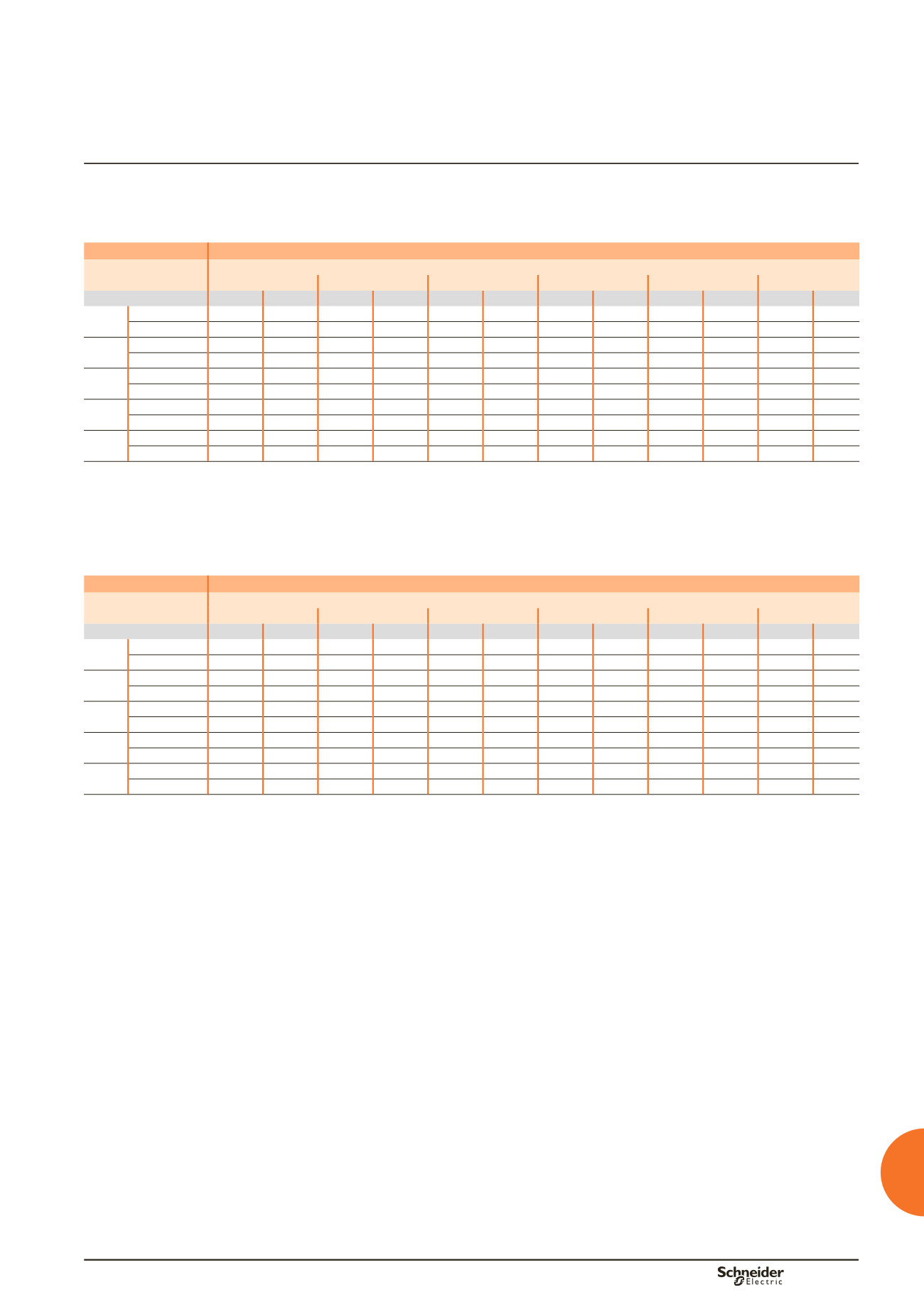
Connection
Flat bars, 10 mm thick
Device
Permissible current (A)
Ambient temperature around the switchboard
25 °C
30 °C
35 °C
40 °C
45 °C
50 °C
IP
y
31 IP > 31 IP
y
31 IP > 31 IP
y
31 IP > 31 IP
y
31 IP > 31 IP
y
31 IP > 31 IP
y
31 IP > 31
NT06 Size per phase 1b 50 x 10 1b 50 x 10 1b 50 x 10 1b 50 x 10 1b 50 x 10 1b 50 x 10 1b 50 x 10 1b 50 x 10 1b 50 x 10 1b 50 x 10 1b 50 x 10
bb
I (A)
630
630
630
630
630
630
630
630
630
630
630
NT08 Size per phase 1b 50 x 10 1b 50 x 10 1b 50 x 10 1b 50 x 10 1b 50 x 10 1b 50 x 10 1b 50 x 10 1b 50 x 10 1b 50 x 10 1b 50 x 10 1b 50 x 10
bb
I (A)
800
800
800
800
800
800
800
800
800
800
800
NT10 Size per phase 1b 50 x 10 1b 50 x 10 1b 50 x 10 1b 50 x 10 1b 50 x 10 1b 50 x 10 1b 50 x 10 1b 50 x 10 1b 50 x 10 1b 50 x 10 1b 50 x 10
bb
I (A)
1000
1000
1000
1000
1000
1000
1000
1000
1000
960
1000
NT12 Size per phase 1b 50 x 10 1b 50 x 10 1b 50 x 10 1b 50 x 10 1b 50 x 10 1b 50 x 10 1b 50 x 10 1b 50 x 10 1b 50 x 10 1b 50 x 10 1b 50 x 10
bb
I (A)
1250
1250
1250
1250
1250
1210
1250
1160
1210
1110
1160
NT16
(1)
Size per phase 2b 50 x 10 2b 50 x 10 2b 50 x 10 2b 50 x 10 2b 50 x 10 2b 50 x 10 2b 50 x 10 2b 50 x 10 2b 50 x 10 2b 50 x 10 2b 50 x 10
bb
I (A)
1560
1430
1520
1430
1480
1380
1430
1330
1380
1280
1330
(1)
Make the neutral connection with one bar, 50 x 10 mm.
bb
Connection impossible due to the operating-temperature limits of the devices installed in the switchboard.
Horizontal link
Flat bars, 10 mm thick
Device
Permissible current (A)
Ambient temperature around the switchboard
25 °C
30 °C
35 °C
40 °C
45 °C
50 °C
IP
y
31 IP > 31 IP
y
31 IP > 31 IP
y
31 IP > 31 IP
y
31 IP > 31 IP
y
31 IP > 31 IP
y
31 IP > 31
NT06 Size per phase 1b 50 x 10 1b 50 x 10 1b 50 x 10 1b 50 x 10 1b 50 x 10 1b 50 x 10 1b 50 x 10 1b 50 x 10 1b 50 x 10 1b 50 x 10 1b 50 x 10
bb
I (A)
630
630
630
630
630
630
630
630
630
630
630
NT08 Size per phase 1b 50 x 10 1b 50 x 10 1b 50 x 10 1b 50 x 10 1b 50 x 10 1b 50 x 10 1b 50 x 10 1b 50 x 10 1b 50 x 10 1b 50 x 10 1b 50 x 10
bb
I (A)
800
800
800
800
800
800
800
800
800
800
800
NT10 Size per phase 1b 50 x 10 1b 50 x 10 1b 50 x 10 1b 50 x 10 1b 50 x 10 1b 50 x 10 1b 50 x 10 1b 50 x 10 1b 50 x 10 1b 50 x 10 1b 50 x 10
bb
I (A)
1000
1000
1000
1000
1000
1000
1000
1000
1000
960
1000
NT12 Size per phase 1b 60 x 10 1b 60 x 10 1b 60 x 10 1b 60 x 10 1b 60 x 10 1b 60 x 10 1b 60 x 10 1b 60 x 10 1b 60 x 10 1b 60 x 10 1b 60 x 10
bb
I (A)
1250
1250
1250
1250
1250
1210
1250
1160
1210
1110
1160
NT16 Size per phase 1b 80 x 10 1b 80 x 10 1b 80 x 10 1b 80 x 10 1b 80 x 10 1b 80 x 10 1b 80 x 10 1b 80 x 10 1b 80 x 10 1b 80 x 10 1b 80 x 10
bb
I (A)
1560
1430
1520
1430
1480
1380
1430
1330
1380
1280
1330
bb
Connection impossible due to the operating-temperature limits of the devices installed in the switchboard.
Note:
The values indicated above have been validated for Prisma P switchboards.
Designing connections between
a device and busbars
Drawout Masterpact NT06 to NT16