


 271 / 338

D-37
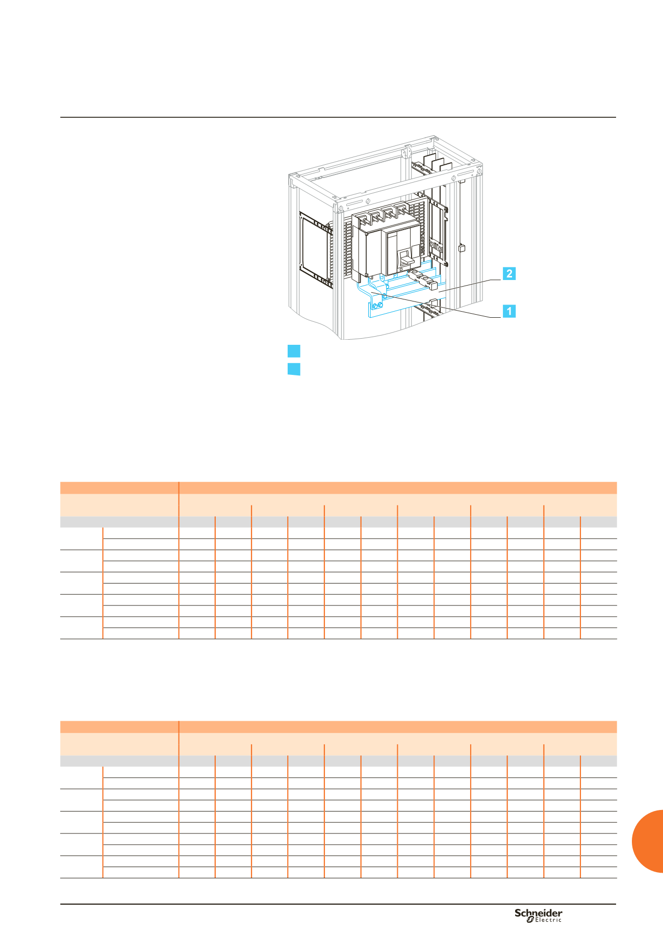
Compact NS630b to NS1600
Fixed
Vertical busbars on the left or right
Linergy BS busbars
Busbar drawings supplied by
Schneider Electric
Dd385492.eps
1
Connection.
2
Horizontal link.
Using the data below, it is possible to determine the size of the copper bars and the
maximum permissible currents when making the connections to busbars for a
vertical, fixed Compact NS630b/NS1600, taking into account the ambient
temperature around the switchboard and the IP value.
Connection
Flat bars, 5 mm thick
Device
Permissible current (A)
Ambient temperature around the switchboard
25 °C
30 °C
35 °C
40 °C
45 °C
50 °C
IP
y
31 IP > 31 IP
y
31 IP > 31 IP
y
31 IP > 31 IP
y
31 IP > 31 IP
y
31 IP > 31 IP
y
31 IP > 31
NS630b Size per phase
1b 50 x 5 1b 50 x 5 1b 50 x 5 1b 50 x 5 1b 50 x 5 1b 50 x 5 1b 50 x 5 1b 50 x 5 1b 50 x 5 1b 50 x 5 1b 50 x 5
bb
I (A)
630
630
630
630
630
630
630
630
630
630
630
NS800
Size per phase
2b 50 x 5 2b 50 x 5 2b 50 x 5 2b 50 x 5 2b 50 x 5 2b 50 x 5 2b 50 x 5 2b 50 x 5 2b 50 x 5 2b 50 x 5 2b 50 x 5
bb
I (A)
800
800
800
800
800
800
800
800
800
800
800
NS1000 Size per phase
2b 50 x 5 2b 50 x 5 2b 50 x 5 2b 50 x 5 2b 50 x 5 2b 50 x 5 2b 50 x 5 2b 50 x 5 2b 50 x 5 2b 50 x 5 2b 50 x 5
bb
I (A)
1000 1000 1000 1000 1000 1000 1000 1000 1000 970
1000
NS1250 Size per phase
3b 50 x 5 3b 50 x 5 3b 50 x 5 3b 50 x 5 3b 50 x 5 3b 50 x 5 3b 50 x 5 3b 50 x 5 3b 50 x 5 3b 50 x 5 3b 50 x 5
bb
I (A)
1250 1250 1250 1250 1250 1250 1250 1200 1250 1150 1200
NS1600
(1)
Size per phase
4b 50 x 5 4b 50 x 5 4b 50 x 5 4b 50 x 5 4b 50 x 5 4b 50 x 5 4b 50 x 5 4b 50 x 5 4b 50 x 5 4b 50 x 5 4b 50 x 5
bb
I (A)
1600 1550 1600 1500 1550 1450 1500 1400 1450 1350 1400
(1)
Make the neutral connection with two bars, 50 x 5 mm.
bb
Connection impossible due to the operating-temperature limits of the devices installed in the switchboard.
Horizontal link
Flat bars, 5 mm thick
Device
Permissible current (A)
Ambient temperature around the switchboard
25 °C
30 °C
35 °C
40 °C
45 °C
50 °C
IP
y
31 IP > 31 IP
y
31 IP > 31 IP
y
31 IP > 31 IP
y
31 IP > 31 IP
y
31 IP > 31 IP
y
31 IP > 31
NS630b Size per phase
1b 60 x 5 1b 60 x 5 1b 60 x 5 1b 60 x 5 1b 60 x 5 1b 60 x 5 1b 60 x 5 1b 60 x 5 1b 60 x 5 1b 60 x 5 1b 60 x 5
bb
I (A)
630
630
630
630
630
630
630
630
630
630
630
NS800
Size per phase
1b 80 x 5 1b 80 x 5 1b 80 x 5 1b 80 x 5 1b 80 x 5 1b 80 x 5 1b 80 x 5 1b 80 x 5 1b 80 x 5 1b 80 x 5 1b 80 x 5
bb
I (A)
800
800
800
800
800
800
800
800
800
800
800
NS1000 Size per phase
2b 50 x 5 2b 50 x 5 2b 50 x 5 2b 50 x 5 2b 50 x 5 2b 50 x 5 2b 50 x 5 2b 50 x 5 2b 50 x 5 2b 50 x 5 2b 50 x 5
bb
I (A)
1000 1000 1000 1000 1000 1000 1000 1000 1000 970
1000
NS1250 Size per phase
2b 60 x 5 2b 60 x 5 2b 60 x 5 2b 60 x 5 2b 60 x 5 2b 60 x 5 2b 60 x 5 2b 60 x 5 2b 60 x 5 2b 60 x 5 2b 60 x 5
bb
I (A)
1250 1250 1250 1250 1250 1250 1250 1200 1250 1150 1200
NS1600 Size per phase
2b 80 x 5 2b 80 x 5 2b 80 x 5 2b 80 x 5 2b 80 x 5 2b 80 x 5 2b 80 x 5 2b 80 x 5 2b 80 x 5 2b 80 x 5 2b 80 x 5
bb
I (A)
1600 1550 1600 1500 1550 1450 1500 1400 1450 1350 1400
bb
Connection impossible due to the operating-temperature limits of the devices installed in the switchboard.
Note:
the values indicated above have been validated for Prisma P switchboards.
Designing connections between
a device and busbars
Fixed Compact NS630b to NS1600
Additional information
Electrical characteristics